an electric iron

A technology for an electric iron and a casing, applied in the field of electric irons, can solve the problems of generating more warm water vapor, affecting the user experience, scratching clothes, etc. Effect

Active Publication Date: 2020-12-08
宁波市聚梦智能科技有限公司
View PDF4 Cites 0 Cited by
  • Summary
  • Abstract
  • Description
  • Claims
  • Application Information

AI Technical Summary

Problems solved by technology

[0003] Existing steam spray type electric irons set spray holes on the bottom electric heating plate to humidify clothes while ironing, so that users do not need to sprinkle water on clothes, but in the actual ironing process, it still exists Some disadvantages, such as the spray hole on it will scratch the clothes during the ironing process, which is easy to cause wear and tear on the clothes, and at the same time, it will generate more warm water vapor during use, which will affect the user's experience

Method used


Image

  • an electric iron
  • an electric iron
  • an electric iron

Examples


Embodiment 1

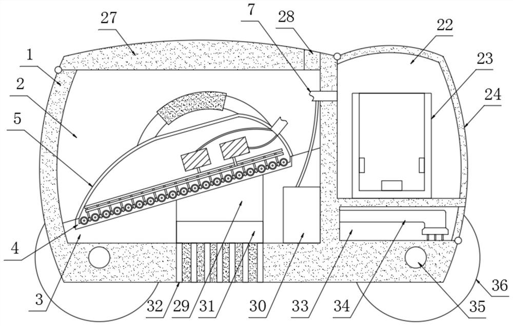
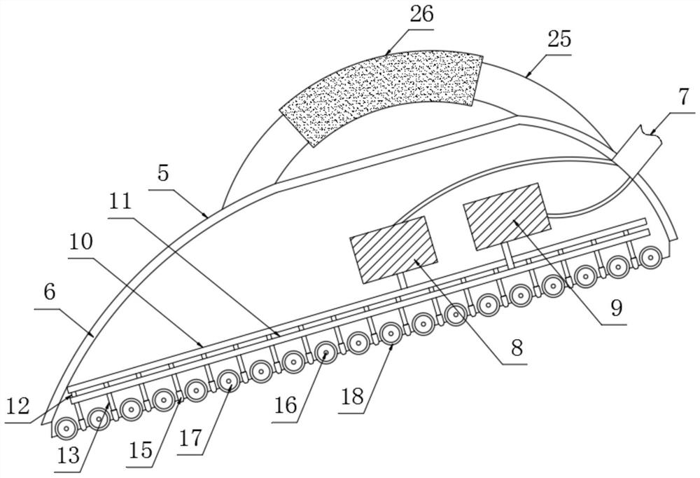
[0026] The present invention provides such Figure 1-4 The shown electric iron includes a first casing 1, a storage chamber 2 is provided inside the first casing 1, a placement seat 3 is provided inside the storage chamber 2, and a placement seat 3 is provided on the top of the placement seat 3. slot 4, the inside of the placement slot 4 is provided with an ironing mechanism 5, the ironing mechanism 5 includes a second casing 6, the side of the second casing 6 is provided with a connecting line 7 and a first fan 8 is provided inside With the second fan 9, the second fan 9 is located on the first fan 8 side, the connecting line 7 is provided with an exhaust pipe 19 and a steam outlet pipe 20, and the exhaust pipe 19 and the outlet pipe 20 Wires 21 are arranged between them, and the bottom of the first fan 8 is provided with a first steam guide pipe 10 and a second steam guide pipe 11, and the second steam guide pipe 11 is arranged inside the first steam guide pipe 10. The bott...

Embodiment 2

[0029] Further, in the above-mentioned embodiment 1, an atomization chamber 22 is provided on the side of the first casing 1, an atomization cup 23 is provided inside the atomization chamber 22, and a heating device is provided on the inner wall of the atomization cup 23. The element and the bottom of the inner chamber are provided with an ultrasonic nebulizer, and the atomization chamber 22 is provided with a sealing cover 24, and the sealing cover 24 is movably connected with the first casing 1 through a hinge.

[0030] Further, in the above-mentioned embodiment 1, a handle 25 is provided on the top of the second casing 6, and an elastic layer 26 is sleeved on the outside of the handle 25, and the elastic layer 26 is made of rubber material. The outer side of the elastic layer 26 is provided with anti-skid lines for users to hold.

[0031] Further, in the above-mentioned embodiment 1, the top cover 27 is provided on the top of the first casing 1, and the top cover 27 is mova...


PUM


Abstract

The invention discloses an electric iron. The electric iron comprises a first machine shell, wherein a storage cavity is formed in the first machine shell; a placement seat is arranged in the storagecavity; a placement groove is formed in the top of the placement seat; an ironing mechanism is arranged in the placement groove; the ironing mechanism comprises a second machine shell; a side face ofthe second machine shell is provided with a connection wire, and the inner part of the second machine shell is provided with a first draught fan and a second draught fan; the second draught fan is arranged at one side of the first draught fan; the connection wire is internally provided with a steam discharging pipe and a steam outlet pipe; a lead wire is arranged between the steam discharging pipeand the steam outlet pipe; a first steam guide pipe and a second steam guide pipe are arranged at the bottom of the first draught fan. According to the electric iron disclosed by the invention, the first draught fan is used for sucking surplus water steam and then the water steam is conveyed into an atomization cavity through the steam discharging pipe again, so that conditions that surplus warmwater enters the air and user experience of a user is influenced are effectively can be effectively prevented, and furthermore, the user can utilize the electric iron more conveniently.

Description

technical field [0001] The invention relates to the technical field of household appliances, in particular to an electric iron. Background technique [0002] An electric iron is a tool for flattening clothes and fabrics, and its power is generally between 300-1000W. Its types can be divided into: ordinary type, temperature adjustment type, steam spray type and so on. Ordinary electric irons are simple in structure, cheap in price, and easy to manufacture and maintain. [0003] Existing steam spray type electric irons set spray holes on the bottom electric heating plate to humidify the clothes while ironing, so that the user does not need to sprinkle water on the clothes, but in the actual ironing process, it still exists Some disadvantages, such as the spray holes on it will scratch the performance of the clothes during the ironing process, which is easy to cause wear and tear on the clothes, and at the same time, it will generate more warm water vapor during use, which af...

Claims


Application Information

Patent Timeline
Patent Type & Authority Patents(China)
IPC IPC(8): D06F75/10D06F75/20D06F75/24D06F75/34D06F75/36D06F75/26
CPCD06F75/10D06F75/20D06F75/24D06F75/26D06F75/34D06F75/36
Inventor 李成锦
Owner 宁波市聚梦智能科技有限公司
Why Eureka
Try Eureka