Cooking device and control method thereof

A cooking device and controller technology, applied in the direction of program control, computer control, general control system, etc., can solve the problems of camera damage, accompanied by oily smoke, oil vapor, adverse effects on camera work reliability, etc., to reduce the risk of early damage effect of possibility

Active Publication Date: 2018-11-30
HANGZHOU ROBAM APPLIANCES CO LTD
View PDF9 Cites 7 Cited by
  • Summary
  • Abstract
  • Description
  • Claims
  • Application Information

AI Technical Summary

Problems solved by technology

[0004] The first object of the present invention is to provide a cooking device, so as to relieve the existing cooking device in the prior art from installing a camera in the cooking chamber. The working reliability of the camera is adversely affected, and it is also easy to cause technical problems of early damage to the camera

Method used


Image

  • Cooking device and control method thereof
  • Cooking device and control method thereof
  • Cooking device and control method thereof

Examples


Embodiment 1

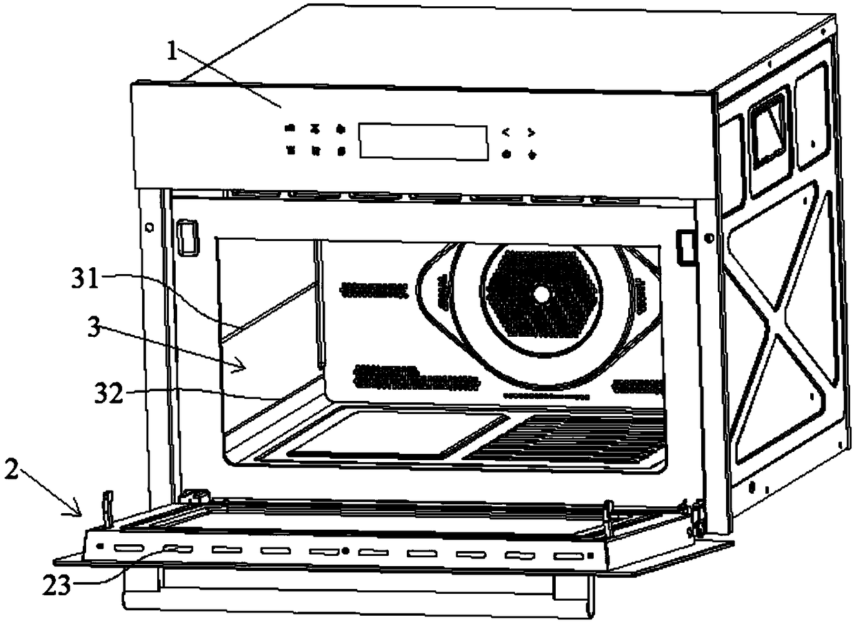
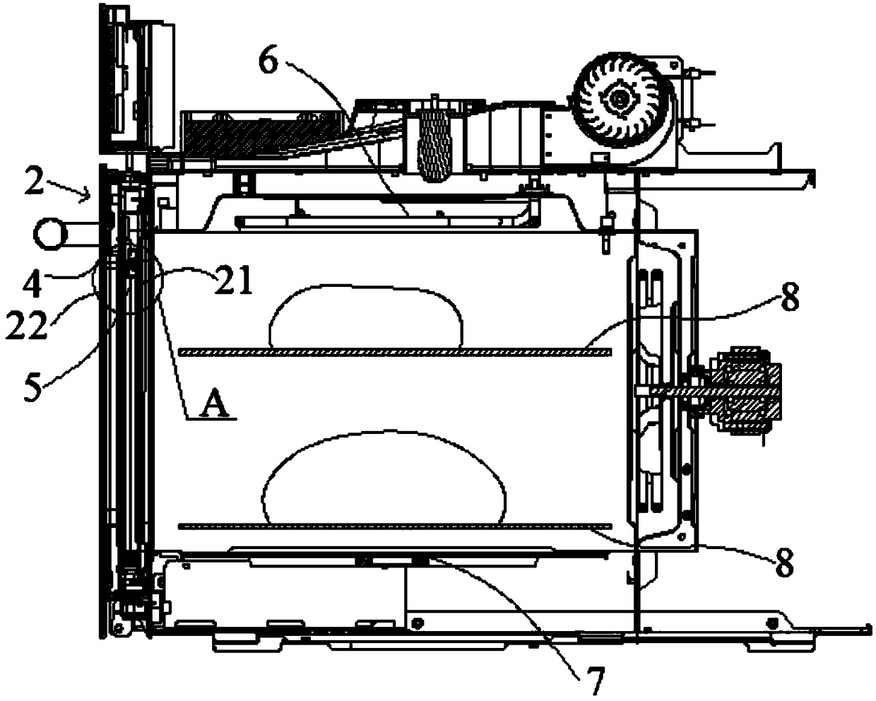
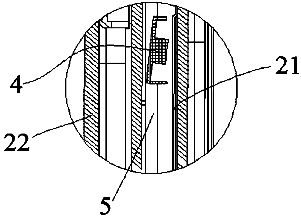
[0058] like figure 1 , figure 2 and Figure 4 As shown, the cooking device provided by this embodiment includes a device body 1 with one side open and a door body 2 capable of covering the open end of the device body 1. An inner container 3 is arranged in the device body 1, and the inner container 3 surrounds the into the cooking chamber of the cooking unit. The door body 2 includes a door frame, an inner door panel 21 arranged in the door frame, and an outer door panel 22 arranged in the door frame. The inner door panel 21 and the outer door panel 22 are arranged at intervals, and an air inlet and a The cavity of the air outlet, wherein the cavity is a part of the cooling air duct. The inner door panel 21 is made of transparent material in whole or in part, and the cooking device also includes a camera assembly 4 and a drive assembly 5. The camera assembly 4 is arranged in the cavity, and the food in the cooking cavity can be photographed through the transparent part 21 o...

Embodiment 2

[0093] The cooking device control method provided in this embodiment is applied to the cooking device provided in Embodiment 1, the method is executed by the controller of the cooking device, and the method includes:

[0094] receiving first detection data of the first detection element, and second detection data of the second detection element;

[0095] generating a second action signal according to the first detection data and the second detection data;

[0096] The second action signal is sent to the driving component 5, so that the driving component 5 performs an operation corresponding to the second action signal.

[0097] The control method of the cooking device provided in this embodiment is applied to the cooking device provided in Embodiment 1, and can achieve the beneficial effects that the above cooking device can achieve, and will not be repeated here.

[0098] In the optional technical solution of this embodiment, the step of the controller generating the second ...


PUM


Abstract

The invention provides a cooking device and a control method thereof, and relates to the technical field of kitchen electrical appliances. The cooking device comprises a device body with one side open, a door body covering the open end of the device body, a camera assembly and a driving assembly, wherein the device body is provided with an inner liner; the door body comprises a door frame, an inner door plate arranged in the door frame, and an outer door plate arranged in the door frame; the inner door plate and the outer door plate are arranged in a spaced manner; a cavity is formed between the inner door plate and the outer door plate; the inner door plate is made of a transparent material; the camera assembly is arranged in the cavity, and can shoot foods in the cooking cavity through the inner door plate; and the driving assembly is used for driving the camera assembly to ascend and descend so as to change the height of the camera assembly. Through adoption of the cooking device, the problems that the working reliability of a camera is adversely affected and early damage of the camera is caused easily since the camera is arranged in the cooking cavity and the cooking cavity hashigh temperature and high humidity and is often accompanied by oil fume, vapor and the like in the cooking device are relieved.

Description

technical field [0001] The invention relates to the technical field of kitchen appliances, in particular to a cooking device and a control method thereof. Background technique [0002] At present, on cooking appliances (such as ovens, steam ovens, steam ovens, or microwave ovens), in order to enable users to more intuitively obtain the cooking status of food in the cooking cavity, cameras are used to take pictures or videos, so that users can The outside of the electrical appliance is convenient to observe the changes of information such as the ripeness and color of the food during the cooking process. However, in the prior art, the cooking device is provided with a camera in the cooking cavity, and the cooking cavity has high temperature, high humidity and is often accompanied by oil fume, oil vapor, etc., which will adversely affect the reliability of the camera, and it is easy to cause the camera to early damage. [0003] Therefore, it is urgent to design a new cooking ...

Claims


Application Information

Patent Timeline
IPC IPC(8): G05B19/042A47J27/00A47J36/00
CPCA47J27/002A47J36/00G05B19/0423G05B2219/2643
Inventor 任富佳唐修豪
Owner HANGZHOU ROBAM APPLIANCES CO LTD
Why Eureka
Try Eureka