
Touch screen and production method thereof

A manufacturing method and touch screen technology, which are applied to instruments, electrical digital data processing, and input/output processes of data processing, etc., can solve the problems of large space occupied by silver paste patterns, wide borders, and damage to silver paste wiring, etc., to achieve Realize the effect of narrow border and simple process

Inactive Publication Date: 2018-11-30
TRULY OPTO ELECTRONICS
View PDF5 Cites 1 Cited by
  • Summary
  • Abstract
  • Description
  • Claims
  • Application Information

AI Technical Summary

Problems solved by technology

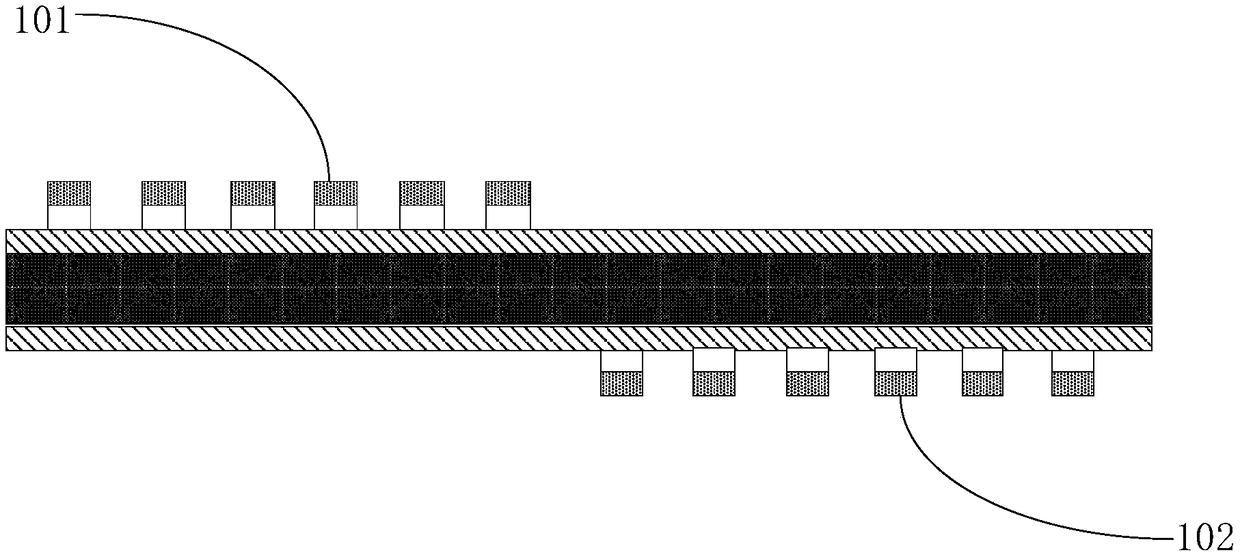
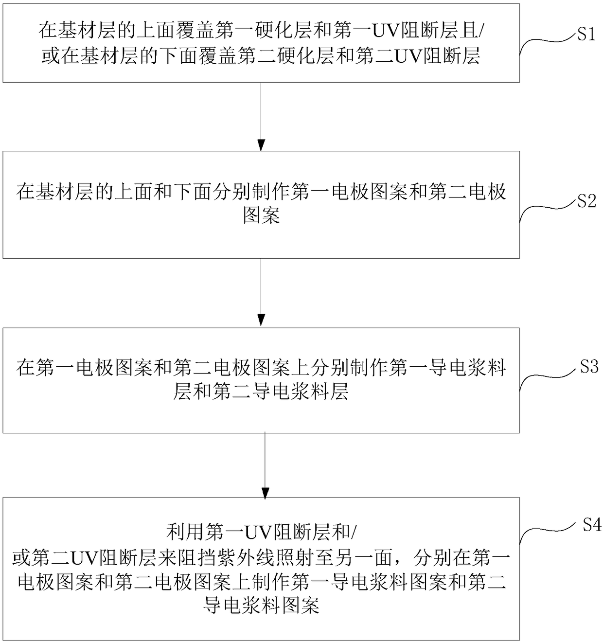
[0003] The touch screen with GF2 structure has been widely concerned by touch screen manufacturers since it was used by Apple. However, when only GF2 structure touch screens are used now, both ITO patterns and copper patterns must be used on both sides. At the same time, the interaction between copper and ITO must be considered. Therefore, The silver paste patterns on both sides should be completely staggered, such as figure 1 as shown, figure 1 It is a schematic diagram of a touch screen in the prior art. It can be seen that the upper first silver paste patterns 101 are all located in the left area, while the lower second silver paste patterns 102 are all located in the right area. It can be seen that all the silver paste patterns occupy a very large space. As a result, the border is wider. For the GF2 structure, if the silver paste on both sides of the substrate layer is not completely staggered in this way and some overlap is allowed, the area occupied by the wiring can be reduced, but another problem arises in this operation, which is the use of laser When engraving the silver paste trace pattern on one side, the light usually passes through the substrate layer and etches to the silver paste trace on the other side, causing damage to the silver paste trace on the other side, which also affects the realization of narrow borders. formed a hindrance

Method used


Image

  • Touch screen and production method thereof
  • Touch screen and production method thereof
  • Touch screen and production method thereof

Examples


Embodiment Construction

[0024] The core of the present invention is to provide a touch screen and a manufacturing method thereof, which can realize the narrow border effect of the touch screen on the basis of a simple process.

[0025] The following will clearly and completely describe the technical solutions in the embodiments of the present invention with reference to the accompanying drawings in the embodiments of the present invention. Obviously, the described embodiments are only some, not all, embodiments of the present invention. Based on the embodiments of the present invention, all other embodiments obtained by persons of ordinary skill in the art without making creative efforts belong to the protection scope of the present invention.

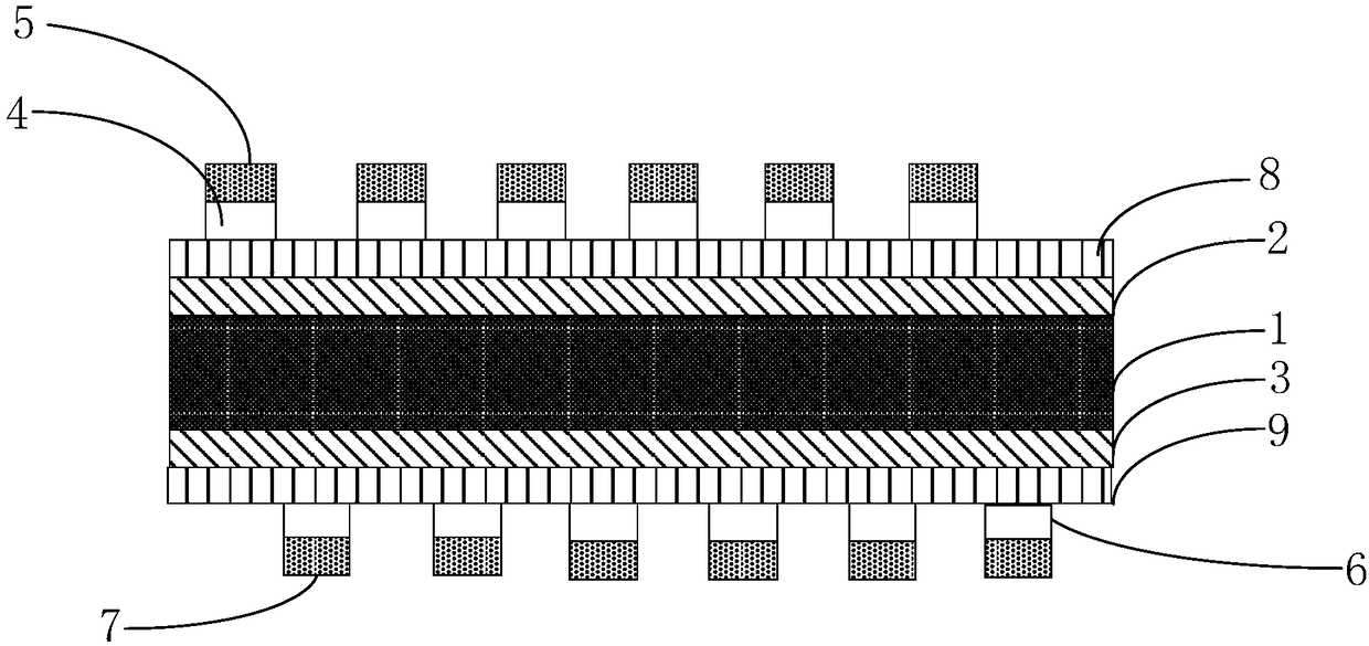
[0026] The touch screen provided by this application is as figure 2 as shown, figure 2 The front view of the touch screen provided for this application includes a substrate layer 1, the upper and lower surfaces of the substrate layer 1 are respectively cov...


PUM


Abstract

The invention discloses a touch screen. The touch screen comprises a base material layer, wherein the upper surface and the lower surface of the base material layer are covered with a first hardeninglayer and a second hardening layer respectively, a first transparent electrode pattern is arranged on the upper surface of the first hardening layer, a first conducting slurry pattern is arranged on the first transparent electrode pattern, a second transparent electrode pattern is arranged on the lower surface of the second hardening layer, a second conducting slurry pattern is arranged below thesecond transparent electrode pattern, a first UV blocking layer is arranged between the base material layer and the first transparent electrode pattern, and / or a second UV blocking layer is arranged between the base material layer and the second transparent electrode pattern, and the first UV blocking layer and / or the second UV blocking layer cover(s) the whole area(s) of the upper surface and / orthe lower surface of the base material layer. Through the touch screen, a narrow border effect of the touch screen can be achieved on the basis of a simple process. The invention furthermore disclosesa production method of the touch screen. Through the method, the narrow border effect of the touch screen can be achieved on the basis of the simple process.

Description

technical field [0001] The invention belongs to the technical field of electronic products, in particular to a touch screen and a manufacturing method thereof. Background technique [0002] The touch screen is an inductive liquid crystal display device that can receive input signals such as contacts. When the graphic buttons on the screen are touched, the tactile feedback system on the screen can drive various connection devices according to pre-written programs, which can be used to replace mechanical The button panel of the style is adopted, and the vivid audio-visual effect is produced by the liquid crystal display screen. Existing touch screens have a variety of structures, including G+G, P+G and GF2. Among them, the G+G structure is composed of surface tempered glass + screen made of glass material, and its structure is sensor glass + tempered glass cover. Part, the main features are hard wear resistance, corrosion resistance, high light transmittance, smooth control, ...

Claims


Application Information

Patent Timeline
IPC IPC(8): G06F3/041
CPCG06F3/0412G06F2203/04103
Inventor 吴德生李志成
Owner TRULY OPTO ELECTRONICS
Learn More