
Efficient mixing equipment for paint production

A stirring device and high-efficiency technology, applied in mixers with rotating containers, dissolving, mixers, etc., can solve the problems of inability to stir the paint in different positions up and down, poor stirring quality, low stirring efficiency, etc., to reduce the difficulty of stirring, Improve mixing efficiency and mixing quality, and enhance the effect of mixing quality

Inactive Publication Date: 2018-12-04
周兆平
View PDF5 Cites 5 Cited by
  • Summary
  • Abstract
  • Description
  • Claims
  • Application Information

AI Technical Summary

Problems solved by technology

[0003] The purpose of the present invention is to overcome the problems of low stirring efficiency, inability to stir the paint at different positions up and down, and poor stirring quality existing in the existing paint stirring equipment, and to provide a kind of convenient operation, high work efficiency, which can carry out different stirring of the paint. High-efficiency mixing equipment for coating production with high mixing, low operating cost, and high mixing uniformity

Method used


Image

  • Efficient mixing equipment for paint production
  • Efficient mixing equipment for paint production
  • Efficient mixing equipment for paint production

Examples


Embodiment 1

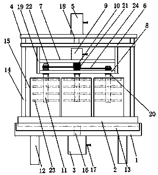
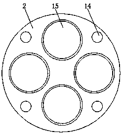
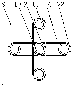
[0018] as attached Figure 1-3 As shown, a high-efficiency mixing equipment for coating production includes a bottom plate 1, a bearing table 2, a motor 3, a top plate 4, a cylinder 5, an adjustment plate 6, a connecting plate 7, a connecting plate 2 8, a motor 2 9, and a rotating shaft 10 and the driven shaft 11, characterized in that: the base plate 1 is arranged on the bracket 12, and a bearing groove 13 is arranged on the base plate 1, and the bearing platform 2 is arranged in the bearing groove 13, and on the bearing platform 2 is provided with a column 14, a mixing bucket 15, the motor one 3 is arranged on the base plate 1, a transmission shaft 16 and a power cord 17 are arranged on the motor one 3, and the transmission shaft 16 is connected with the carrying platform 2, so The top plate 4 is arranged on the column 14, the cylinder 5 is arranged on the top plate 4, and the power cord 17 and the piston rod 18 are arranged on the cylinder 5, and the adjusting plate 6 is ar...

Embodiment 2

[0024] as attached Figure 4 As shown, a high-efficiency mixing equipment for coating production includes a bottom plate 1, a bearing table 2, a motor 3, a top plate 4, a cylinder 5, an adjustment plate 6, a connecting plate 7, a connecting plate 2 8, a motor 2 9, and a rotating shaft 10 and the driven shaft 11, characterized in that: the base plate 1 is arranged on the bracket 12, and a bearing groove 13 is arranged on the base plate 1, and the bearing platform 2 is arranged in the bearing groove 13, and on the bearing platform 2 is provided with a column 14, a mixing bucket 15, the motor one 3 is arranged on the base plate 1, a transmission shaft 16 and a power cord 17 are arranged on the motor one 3, and the transmission shaft 16 is connected with the carrying platform 2, so The top plate 4 is arranged on the column 14, the cylinder 5 is arranged on the top plate 4, and the power cord 17 and the piston rod 18 are arranged on the cylinder 5, and the adjusting plate 6 is arra...


PUM


Abstract

The invention discloses efficient mixing equipment for paint production, which comprises a bottom plate, a bearing platform, a motor 1, a top plate, a cylinder, a regulating plate, a connecting plate1, a connecting plate 2, a motor 2, a rotating shaft and driven shafts. The efficient mixing equipment is characterized in that the bottom plate is arranged on a bracket, the bearing platform is arranged in a bearing groove, the motor 1 is arranged on the bottom plate, the top plate is arranged on upright columns, and the connecting plate 1 and the connecting plate 2 are arranged between fixed plates. The regulating plate is arranged as a structure that can rise or fall along the upright columns, the regulating plate rises or falls along the upright columns under the action of the cylinder anda piston rod, so as to drive the connecting plate 1 and the connecting plate 2 between the fixed plates to rise or fall, and then drive the motor 2, the rotating shaft and the driven shafts to rise or fall, so that mixing rods on the driven shafts can perform mixing on paint in a mixing barrel at different heights, thereby improving the mixing efficiency of the paint.

Description

technical field [0001] The invention relates to the technical field of paint processing, in particular to high-efficiency stirring equipment for paint production. Background technique [0002] In the process of paint processing, it is necessary to stir the paint. The existing stirring equipment is usually composed of a stirring blade and a stirring shaft. As a result, the stirring equipment can only stir the paint in one direction, which reduces the uniformity of the paint stirring. For example, the patent application number 201710106125.6 discloses a paint mixing tank, which solves the problem of poor drainage of the paint, but it has low stirring efficiency of the paint, cannot stir the paint at different positions up and down, and the stirring quality is not good. The problem. Contents of the invention [0003] The purpose of the present invention is to overcome the problems of low stirring efficiency, inability to stir the paint at different positions up and down, and...

Claims


Application Information

Patent Timeline
IPC IPC(8): B01F9/12B01F11/00B01F13/10B01F29/83
CPCB01F29/82B01F29/83B01F31/40B01F33/813B01F2101/30
Inventor 周兆平张强汪永生
Owner 周兆平
Learn More