
Film cutting machine

A film cutting machine and cutting knife technology, applied in metal processing and other directions, can solve the problems of high labor intensity, low production efficiency, and not suitable for mass production

Pending Publication Date: 2018-12-04
XIAMEN TANUO OPTICAL TECH
View PDF0 Cites 1 Cited by
  • Summary
  • Abstract
  • Description
  • Claims
  • Application Information

AI Technical Summary

Problems solved by technology

The traditional lens processing process is mostly processed by manual cutting. The labor intensity of the workers is high and the production efficiency is low, which is not suitable for mass production.

Method used


Image

  • Film cutting machine

Examples


Embodiment Construction

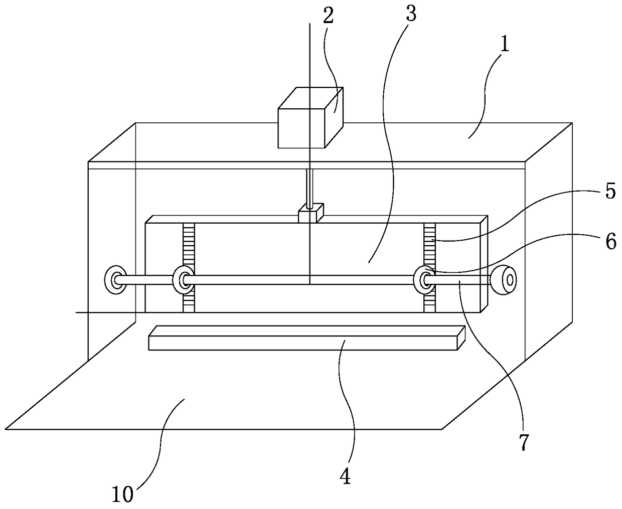
[0009] Such as figure 1 As shown, the present invention is a film cutting machine, including a cutter frame 1, a cutter cylinder 2, a cutter 3, a knife seat 4, two guide racks 5, two guide gears 6, and a guide shaft 7.

[0010] The cutter frame 1 is fixedly bridged on the frame 10, the cylinder block of the cutter cylinder 2 is fixedly mounted on the top of the cutter frame 1, and the piston rod end of the cutter cylinder 2 passes through the cutter frame 1 downwards. Connect with the upper end of cutter 3 afterward, the lower end of cutter 3 stretches to knife seat 4, and knife seat 4 is fixed on the frame 10; Described two guide racks 5 are installed on the side wall of cutter 3 respectively, The two guide gears 6 are fixedly sleeved on the guide shaft 7 and the two guide gears 6 are meshed with the two guide racks 5 respectively, so that the cutter 3 moves up and down more smoothly, and the guide shaft 7 is rotatably installed on the cutter frame 1 superior.

[0011] Work...


PUM


Abstract

The invention discloses a film cutting machine. The film cutting machine comprises a cutter rest, a cutter cylinder, a cutter, a cutter holder, two guide racks, two guide gears and a guide shaft; thecutter rest is fixedly connected to a machine frame in an across mode; a cylinder block of the cutter cylinder is fixedly mounted at the top of the cutter rest; the rod end of a piston rod of the cutter cylinder downwards penetrates through the cutter rest and then is connected with the upper end of the cutter; the lower end of the cutter extends to the cutter holder; the cutter holder is fixed onthe machine frame; the two guide racks are mounted on the side wall of the cutter; the two guide gears are fixedly arranged on the guide shaft in a sleeving mode and engaged with the two guide rackscorrespondingly; and the guide shaft is rotationally mounted on the cutter rest. Due to the fact that the two guide racks are mounted on the side wall of the cutter, the two guide racks can be engagedwith the two guide gears, thus, the cutter can be stabilized in the film cutting process, and a film is cut more stably and accurately.

Description

technical field [0001] The invention relates to a lens production equipment, in particular to a film cutting machine. Background technique [0002] Lenses are the main components of glasses. In the traditional lens processing process, most of them are processed by manual cutting. The labor intensity of workers is high and the production efficiency is low, which is not suitable for mass production. Contents of the invention [0003] The object of the present invention is to provide a stable and accurate film cutting machine for cutting film. [0004] For realizing the above object, technical solution of the present invention is: [0005] The invention relates to a film cutting machine, comprising a cutter frame, a cutter cylinder, a cutter, a knife seat, two guide racks, two guide gears, and a guide shaft; the cutter frame is fixedly connected to the frame On the top, the cylinder body of the cutter cylinder is fixedly installed on the top of the cutter frame, the piston...

Claims


Application Information

Patent Timeline
IPC IPC(8): B26D1/08B26D5/12B26D7/00
CPCB26D1/08B26D5/12B26D7/00
Inventor 周杨
Owner XIAMEN TANUO OPTICAL TECH
Learn More