Electric bicycle outdoor protective type safety charging equipment and use method thereof

A charging equipment and external protection technology, which is applied to the field of outdoor protective safety charging equipment for electric bicycles, can solve the problem of not considering the protection function of electric bicycles, and achieve the effects of high protection effect, scientific design and strong practicability

Pending Publication Date: 2018-12-04
河南境颐物业服务有限公司
View PDF7 Cites 2 Cited by
  • Summary
  • Abstract
  • Description
  • Claims
  • Application Information

AI Technical Summary

Problems solved by technology

[0004] At present, the electric bicycle charging pile industry has achieved great development in terms of smart payment methods, but the existing electric bicycle charging piles do not consider the protection function of electric bicycles

Method used


Image

  • Electric bicycle outdoor protective type safety charging equipment and use method thereof
  • Electric bicycle outdoor protective type safety charging equipment and use method thereof
  • Electric bicycle outdoor protective type safety charging equipment and use method thereof

Examples


Embodiment 1

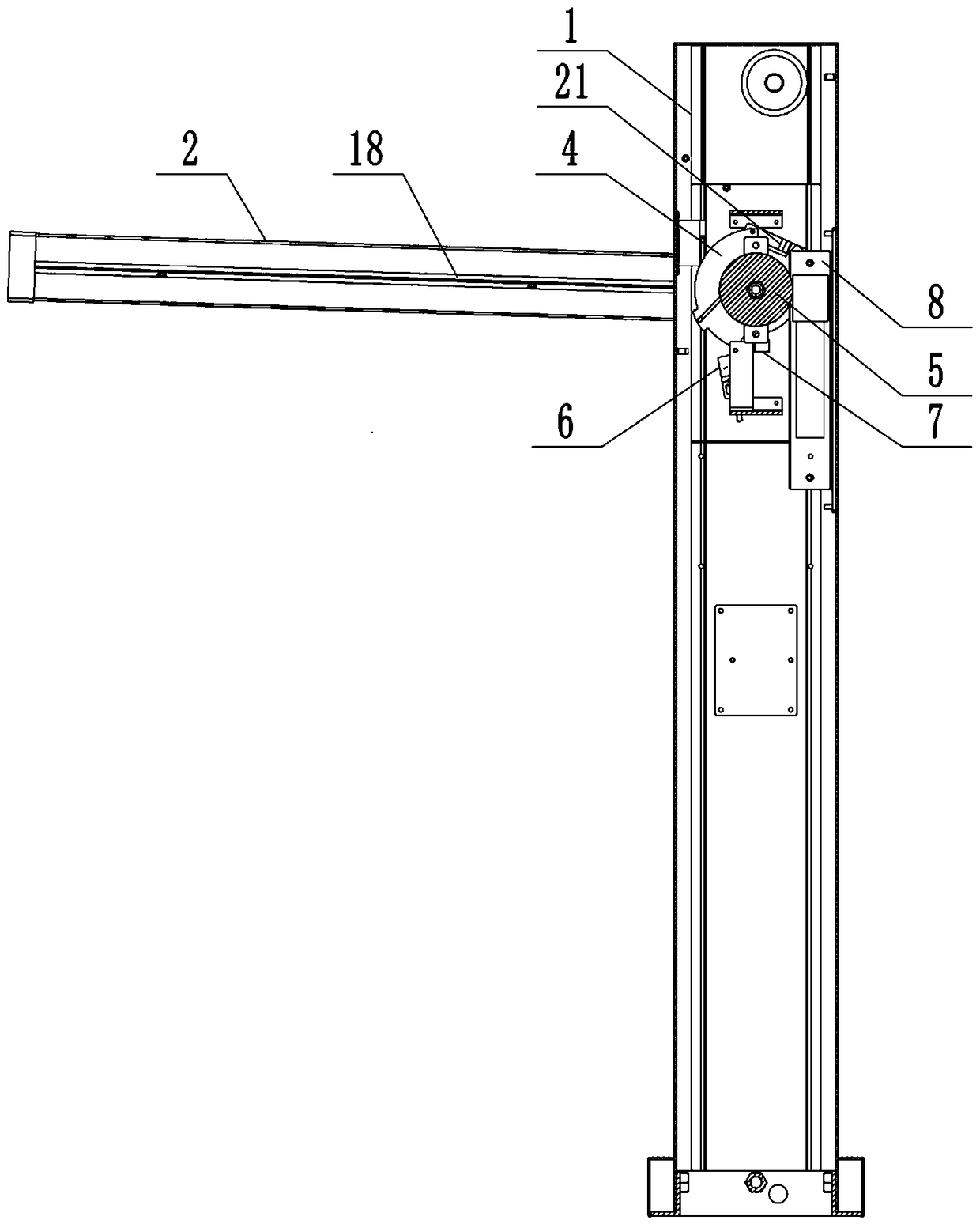
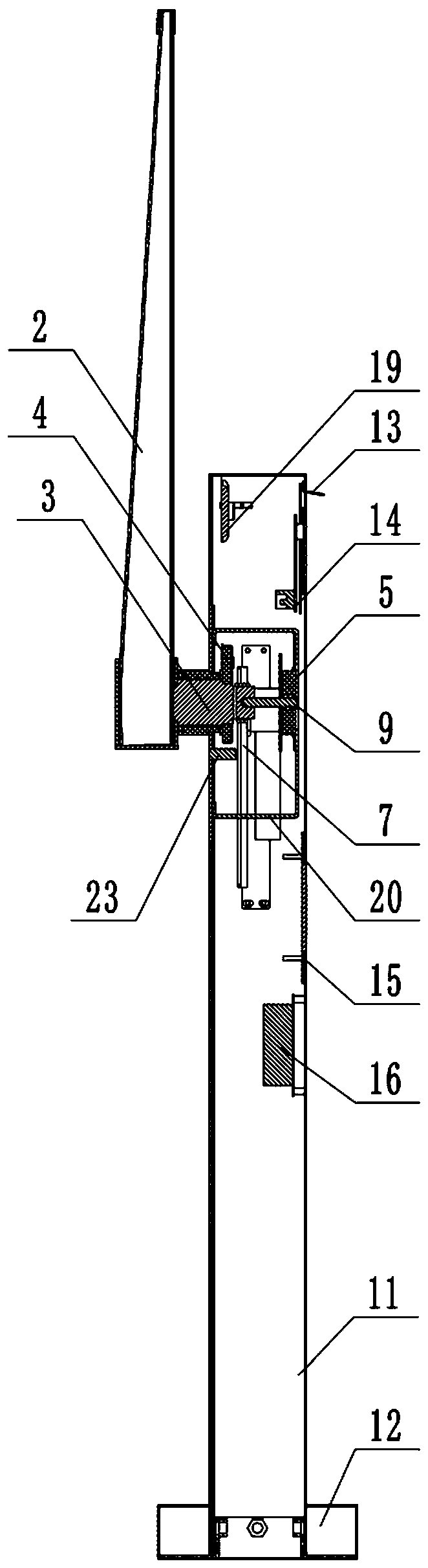
[0041] as attached figure 1 - attached Figure 5 As shown, an outdoor protective safety charging device for a motorcycle, which includes a charging pile 1, a main control box 14 arranged on the charging pile 1, and a protective bar 2, the protective bar 2 is limited by a rotation The mechanism is set on the charging pile 1; the rotation limit mechanism includes a main shaft 3 and a limit wheel 4;

[0042] The main shaft 3 is rotatably installed in the charging pile 1, one end of the main shaft 3 protrudes from the charging pile 1 and is fixedly connected with one end of the protective bar 2, and the other end of the main shaft 3 is fixedly connected The limit runner 4;

[0043] The bottom of the limit runner 4 is provided with a stop pin 7, and the side is provided with an electromagnetic lock 8; the electromagnetic lock 8 is connected with the main control box 14 in communication to receive and execute the control command of the main control box 14 ; The outer edge of the ...

Embodiment 2

[0052] The difference between this embodiment and Embodiment 1 is that a torsion spring 10 is sheathed on the main shaft 3, one end of the torsion spring 10 is fixed on the edge of the limit runner 4, and the other end is fixed on the charging On the inner wall of the pile; the outer edge of the limit runner 4 is also provided with a second limit notch 41 on the same side as the first limit notch 43, and one end of the second limit notch 41 is connected to the first limit notch 43. One end of the first limit notch 43 is correspondingly arranged at 180°; when the protection bar 2 is in the vertical position, the protruding bolt of the electromagnetic lock 8 is engaged in the second limit notch 41, Prevent described protection bar 2 from falling down automatically.

[0053] The difference between this embodiment and the working process of Embodiment 1 is: (1) When the protection bar 2 is in the vertical position, the electromagnetic lock 8 stretches out the lock tongue to lock t...

Embodiment 3

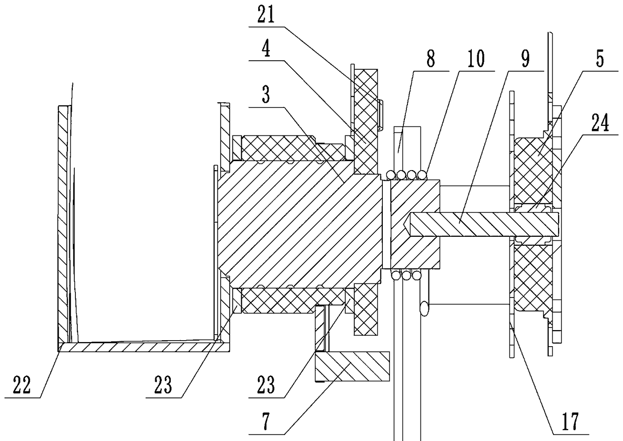
[0060] The difference between this embodiment and Embodiment 1 is that the other end of the main shaft 3 is connected to a rotary damper 5 through an optical axis 9 , and the rotary damper 5 is fixedly arranged in the charging pile 1 . The optical axis 9 is connected to the rotary damper 5 through a one-way bearing 24, and during the process of the protective bar 2 returning to the horizontal position from the vertical position, the viscous oil in the rotary damper 5 will affect the optical axis. 9 and the rotation of the main shaft 3 play a resistance role, which in turn affects the motion state of the protective bar 2; the rotation damper 5 increases the stability of the action of the protective bar 2, reaching the The effect of falling slowly increases the stability of this embodiment and prolongs the service life of this embodiment.

[0061] In order to further increase the stability of this embodiment, the main shaft 3 is connected to the protective bar 2 through a bushin...


PUM


Abstract

The invention provides electric bicycle outdoor protective type safety charging equipment and a use method thereof. The electric bicycle outdoor protective type safety charging equipment comprises a charging pile, a main control box and a protective stopping rod, wherein the main control box is arranged on the charging pile; the protective stopping rod is arranged on the charging pile through a rotary limiting mechanism; the rotary limiting mechanism comprises a main shaft and a limiting rotating wheel; the main shaft is mounted in the charging pile in a rotatable manner; one end of the main shaft extends out of the charging pile to be fixedly connected with one end of the protective stopping rod; the other end of the main shaft is fixedly connected with the limiting rotating wheel; a stopping pin is arranged under the limiting rotating wheel; an electromagnetic lock is arranged on the side surface of the limiting rotating wheel; the electromagnetic lock is in communication connectionwith the main control box to receive and execute a control command of the main control box; and a first limiting gap is formed in the outer edge of the limiting rotating wheel. The electric bicycle outdoor protective type safety charging equipment and the use method thereof have the advantages of scientific design, strong practicability, high protective effect and low production cost.

Description

technical field [0001] The invention relates to the technical field of electric bicycle charging equipment, in particular, relates to an outdoor protective type safety charging equipment for electric bicycles and a method for using the same. Background technique [0002] In recent years, with the increasing tension of global energy, saving energy has become the focus of the whole society. In this regard, many scientists and politicians from all walks of life also held a climate conference, calling on people all over the world to protect our homeland. There is no doubt that bicycles are the most environmentally friendly means of transportation, and electric bicycles are becoming more and more popular among citizens, and charging piles for electric bicycles have also entered the public's field of vision. [0003] Electric bicycles have many advantages that other means of transportation do not have, such as convenience, economy and environmental protection. Under the strong ap...

Claims


Application Information

Patent Timeline
Patent Type & Authority Applications(China)
IPC IPC(8): B60L11/18H02J7/00
CPCH02J7/0027B60L2200/46
Inventor 苏艳娟范长森李伟张晓
Owner 河南境颐物业服务有限公司
Why Eureka
Try Eureka