Cutting device for web winder

A technology of fiber web and winding machine, applied in winding mechanism, fiber processing, winding strip, etc., can solve the problems of difficult sensing to obtain cutter, expensive electric wire guidance, poor operability, etc., to achieve Insignificant cost, reliable replacement, less error effect

Active Publication Date: 2020-06-26
TRUETZSCHLER GRP SE
View PDF8 Cites 0 Cited by
  • Summary
  • Abstract
  • Description
  • Claims
  • Application Information

AI Technical Summary

Problems solved by technology

The disadvantage is that it is difficult to obtain the position of the cutter sensor
Furthermore, the known electrodynamic displacement sensors have the disadvantage that the required electrical lines can only be routed very expensively from the outside to the individual displacement sensors
The non-contact transmission sensor can only use the battery solution, and the operability is deteriorated due to the need to replace the battery or storage battery

Method used


Image

  • Cutting device for web winder
  • Cutting device for web winder
  • Cutting device for web winder

Examples


Embodiment Construction

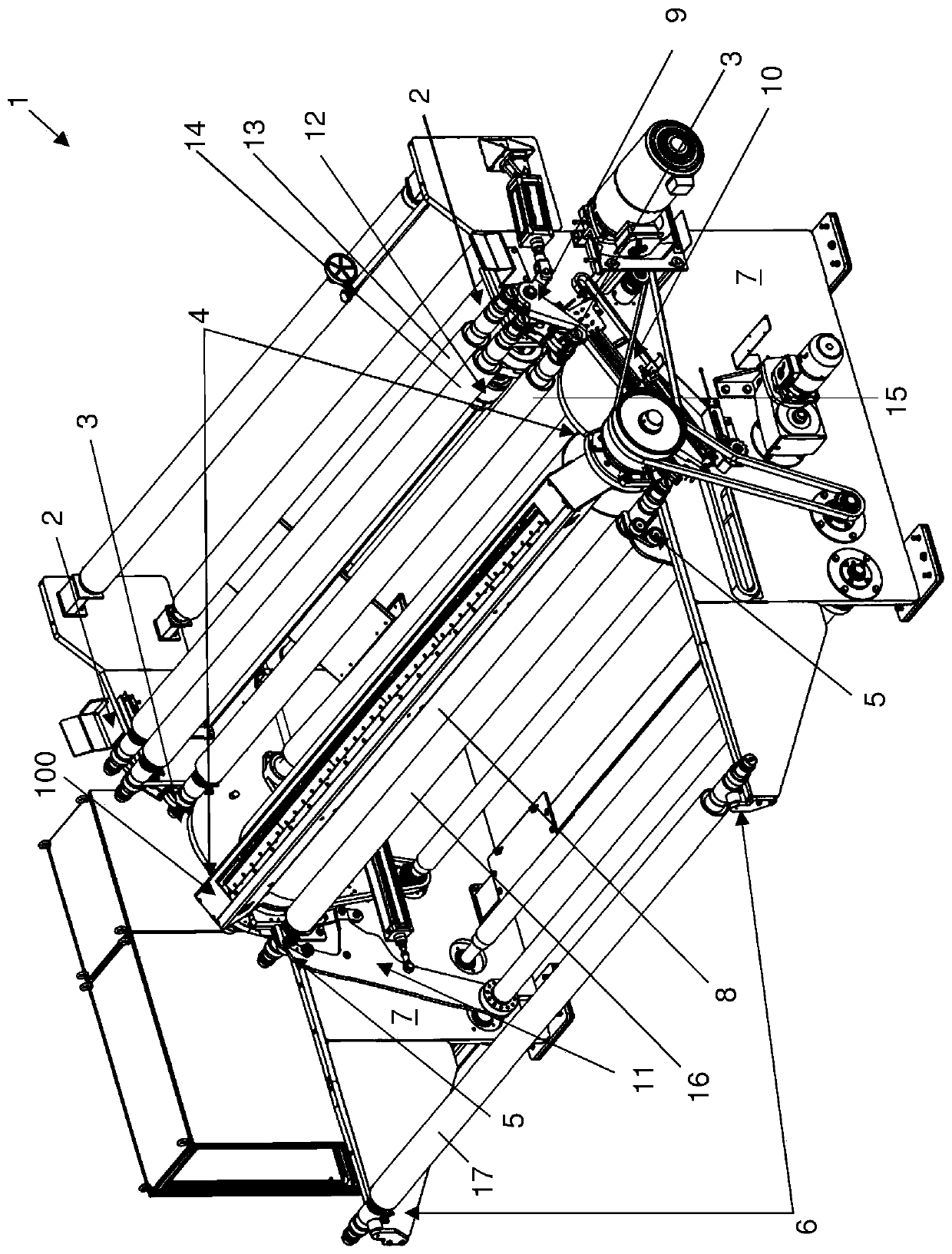
[0026] figure 1 A web winding machine 1 according to an embodiment of the invention is shown. Components that are not essential to the present invention will not be explained in detail.

[0027] The web winding machine 1 essentially comprises two frame walls 7 , which form a frame, which accommodates or fixes all other functional components of the web winding machine 1 , via connecting bodies not shown.

[0028] In the area on the right, the machine frame wall 7 has a depository 2 , in which there are, for example, two winding shafts 13 , 14 .

[0029] The web winder 1 also comprises a recess on each frame wall 7 defining a waiting position 3 for the winding shaft 15 . Since in particular the winding shaft 15 is held on both sides by the frame walls 7 , the waiting position 3 is realized with the two frame walls 7 . The machine frame wall 7 thus forms, with the waiting position 3 , a holding section for the winding shaft 15 to be wound.

[0030] In the waiting position 3 , t...


PUM


Abstract

A device which can be incorporated into a web winding machine (1) for separating webs. The cutting section (106) of the separating section (100) extends across the width of the fiber web and is positionally fixed or vibratingly driven with respect to the axis of rotation of the contact roll (8) around which holding sections (130, 140) are rotatably arranged. The handling segments (102, 104, 105) seat the cutting segments in the holding segments, whereby the cutting segments do not come into contact with the fiber web. The cutting segment is moved transversely to the axis of rotation of the device in such a way that the cutting segment presses the fiber web for separation. A sensor system (160) is used to detect at least one state of the separation section. The fiber web winder winds the fiber web on the winding shaft by means of contact rollers and pressing elements. The pressing element presses the winding shaft against the contact roller so that the fiber web is wound on the winding shaft guided around a part of the circumference of the contact roller. The winder separates the web with the device and monitors the position of the cutting section. The invention also relates to a method for operating a winder.

Description

technical field [0001] The invention relates to a device for a web winding machine which is capable of separating the web when changing the winding shaft to be wound. The invention also relates to a web winding machine equipped with such a device and to a method for such a web winding machine. Background technique [0002] Fiber web winders are known per se. They are used for winding fiber webs, eg from cards, onto winding shafts. For this purpose, the empty winding shafts are wound one after the other in an automatic exchange. This is accomplished by directing the incoming web material around rotating contact rolls. An empty winding shaft provided with an adhesive surface and rotating in the opposite direction to the touch roll rests against the touch roll and receives the fiber web from the touch roll due to adhesion. If this winding shaft is full, a new, empty winding shaft is pressed against the contact roller. In this case, the fiber web still wound up on the prece...

Claims


Application Information

Patent Timeline
Patent Type & Authority Patents(China)
IPC IPC(8): B65H19/26B26D1/12D01G27/00D06H7/02
CPCB26D1/12B65H19/265D01G27/00D06H7/02B65H2701/19B26D1/0006B26D1/08B26D1/085B26D1/42B26D1/425B26D5/02B26D5/12B26D5/14B65H19/2261B65H19/26B65H18/06B65H18/16B65H2301/41816B65H2301/51532B65H2408/236B65H2555/11B65H2701/177
Inventor 克吕斯托夫·巴尔洛克托比亚斯·藏克
Owner TRUETZSCHLER GRP SE
Why Eureka
Try Eureka