Water-cooling fan

A cooling fan and water cooling technology, applied in mechanical equipment, machines/engines, liquid fuel engines, etc., can solve the problems of low cooling efficiency, inability to transmit cold air, and the influence of high temperature shafts, so as to improve service life and improve stability. Effect

Inactive Publication Date: 2018-12-04
张跃
View PDF5 Cites 1 Cited by
  • Summary
  • Abstract
  • Description
  • Claims
  • Application Information

AI Technical Summary

Problems solved by technology

Therefore, the existing water-cooled shaft seat mainly solves the problem of the life of the shaft in a medium-high temperature environment, and the shaft extending into the high-temperature area will not be cooled as a whole, especially the part of the shaft near the center of the fan impeller will not be cooled. The high temperature of the fan impeller will affect the shaft
[0003] In addition, the existing water-cooled shaft seat usually has a hole on its front side, that is, the front side, to install the bearing. Since the height of the shaft seat is usually greater than the thickness of the shaft seat, the shaft passes through the shaft seat along the thickness path of the shaft seat. In this way, The cooling area of ​​the shaft is smaller, and the cooling efficiency is obviously lower
[0004] Furthermore, the distance between the existing water-cooled shaft seat and the fan impeller is relatively large, so that the axial length between the two is relatively large, which will reduce the stability of the fan impeller when it rotates
[0005] In addition, the existing shafts are generally solid shafts, which cannot transmit the cold air flow, but can only spread on the outside of the shaft, so that the shaft cannot be cooled quickly, and the part of the shaft far away from the water-cooled shaft seat basically does not need much cooling. , will still produce overheating, which will greatly reduce the mechanical properties and service life of the shaft

Method used


Image

  • Water-cooling fan
  • Water-cooling fan
  • Water-cooling fan

Examples


Embodiment 1

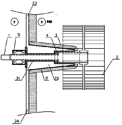
[0032] like figure 1 Shown: a water-cooled fan, including a shaft 1, a bearing and a water-cooled main body, the shaft 1 is connected to the fan impeller 2; The part of the shaft in the high temperature zone passes through the inner cavity of the water-cooled main body.

[0033]In this embodiment, the main body of the water cooling is the shaft seat 3, and the bearing includes an inner bearing 4 and an outer bearing 5, and the inner bearing 4 is located in the high temperature zone of the furnace body, and the outer bearing 5 is arranged outside the furnace body. Since the fan impeller 2 is relatively large, the bearing capacity is greatly improved by arranging inner and outer bearings. In addition, due to the existing high-temperature fans, the shaft seat is generally far away from the fan impeller, so that the shaft between the bearing and the fan impeller is relatively long, resulting in poor stability of the fan during rotation. Therefore, the present embodiment has take...

Embodiment 2

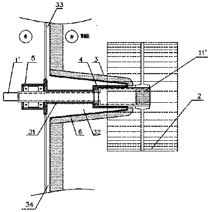
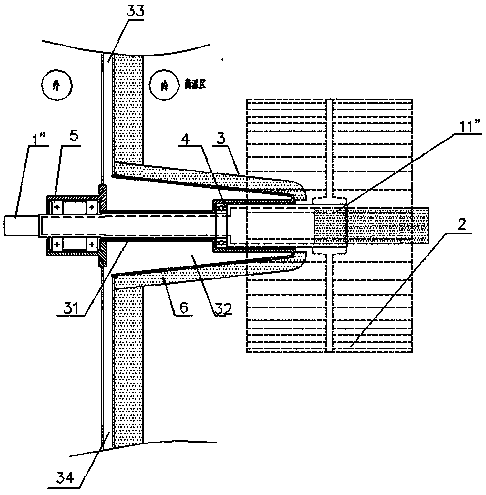
[0041] Such as figure 2 Shown: On the basis of Example 1, the shaft 1' of this embodiment is a hollow shaft, and the hollow shaft is provided with an insulating material 11', and the insulating material 11' is filled on the top of the hollow shaft, that is, the shaft 1' and the The position of the connection of fan impeller 2. The thermal insulation material 11' of the present embodiment is rock wool.

[0042] By arranging the thermal insulation material 11' in the shaft 1', especially the thermal insulation material 11' at the top of the shaft 1', that is, the end close to the center of the fan impeller 2, on the one hand, because the shaft seat 3 is close to the center of the fan impeller However, the cooling effect of the top of the shaft is slightly worse than that of other positions of the shaft. By filling the top with insulation material 11', a certain heat insulation effect can be achieved; on the other hand, due to the high temperature of the fan impeller 2 , then ...

Embodiment 3

[0045] The difference from Embodiment 1 or Embodiment 2 is that a fan casing is provided outside the fan impeller, and the fan casing is connected to the shaft seat.

[0046] Other structures are with embodiment 1 or embodiment 2.


PUM


Abstract

A water-cooling fan comprises a shaft and a water-cooling main body. The shaft is connected with a fan impeller; the water-cooling main body is arranged on the position close to the fan impeller; a water-cooling jacket is arranged in an inner cavity of the water-cooling main body; and the part, extending into a high-temperature area, of the shaft penetrates through the inner cavity of the water-cooling main body. According to the water-cooling fan, on the one hand, the length of the shaft between the water-cooling main body and the fan impeller is shortened by forwards moving the water-coolingmain body, and thus the stability of rotating of the fan impeller is greatly improved; and on the other hand, the part, extending into the high-temperature area, of the shaft can be cooled completely, that is, the whole part, extending into the high-temperature area, of the shaft is not damaged or broken due to overheating, the mechanical properties of the shaft are also not affected, and the service life of the shaft is greatly prolonged.

Description

technical field [0001] The invention relates to the field of high-temperature fans, in particular to a water-cooled fan. Background technique [0002] The water-cooled shaft seat of the existing high-temperature fan is usually installed away from the fan impeller, or installed on the lower side of the fan impeller. Basically, the temperature the shaft bears is below 500°C, that is, the existing water-cooled shaft seat is suitable for medium and high temperature occasions . Therefore, the existing water-cooled shaft seat mainly solves the problem of the life of the shaft in a medium-high temperature environment, and the shaft extending into the high-temperature area will not be cooled as a whole, especially the part of the shaft near the center of the fan impeller will not be cooled. The high temperature of the fan impeller affects the shaft. [0003] In addition, the existing water-cooled shaft seat usually has a hole on its front side, that is, the front side, to install ...

Claims


Application Information

Patent Timeline
Patent Type & Authority Applications(China)
IPC IPC(8): F04D25/08F04D29/58F04D29/053F04D29/056
CPCF04D25/08F04D29/053F04D29/056F04D29/584F04D29/5853
Inventor 张跃
Owner 张跃
Why Eureka
Try Eureka