Supercharge Your Innovation With Domain-Expert AI Agents!

A transmission mechanism based on gear adjustment

A transmission mechanism and gear technology, applied to transmission parts, belts/chains/gears, mechanical equipment, etc., can solve problems such as reducing the transmission effect

Active Publication Date: 2021-09-10
NINGBO POWERNICE INTELLIGENT TECH CO LTD
View PDF18 Cites 0 Cited by
  • Summary
  • Abstract
  • Description
  • Claims
  • Application Information

AI Technical Summary

Problems solved by technology

During the use of the traditional transmission mechanism, when the load on the output shaft is large or even stuck, the drive motor needs to pay a large driving force to drive or be stuck, and the drive motor may be stuck under long-term overload work Finally, it will cause internal overheating and burn it out; to solve the above load problem, we can design a transmission mechanism through friction transmission, which can allow the friction transmission to slip when the load is too large or the load exceeds the critical transmission torque of the friction transmission mechanism. Under normal circumstances, the drive motor can maintain rotation to prevent the drive motor from being stuck and burned out. In addition, in this friction-based transmission mechanism, the drive force is transmitted between the input shaft and the output shaft through friction blocks, and the friction block and output shaft are transmitted through friction. The friction block will be worn after a long time of use, reducing the transmission effect

Method used


Image

  • A transmission mechanism based on gear adjustment
  • A transmission mechanism based on gear adjustment
  • A transmission mechanism based on gear adjustment

Examples


specific Embodiment approach

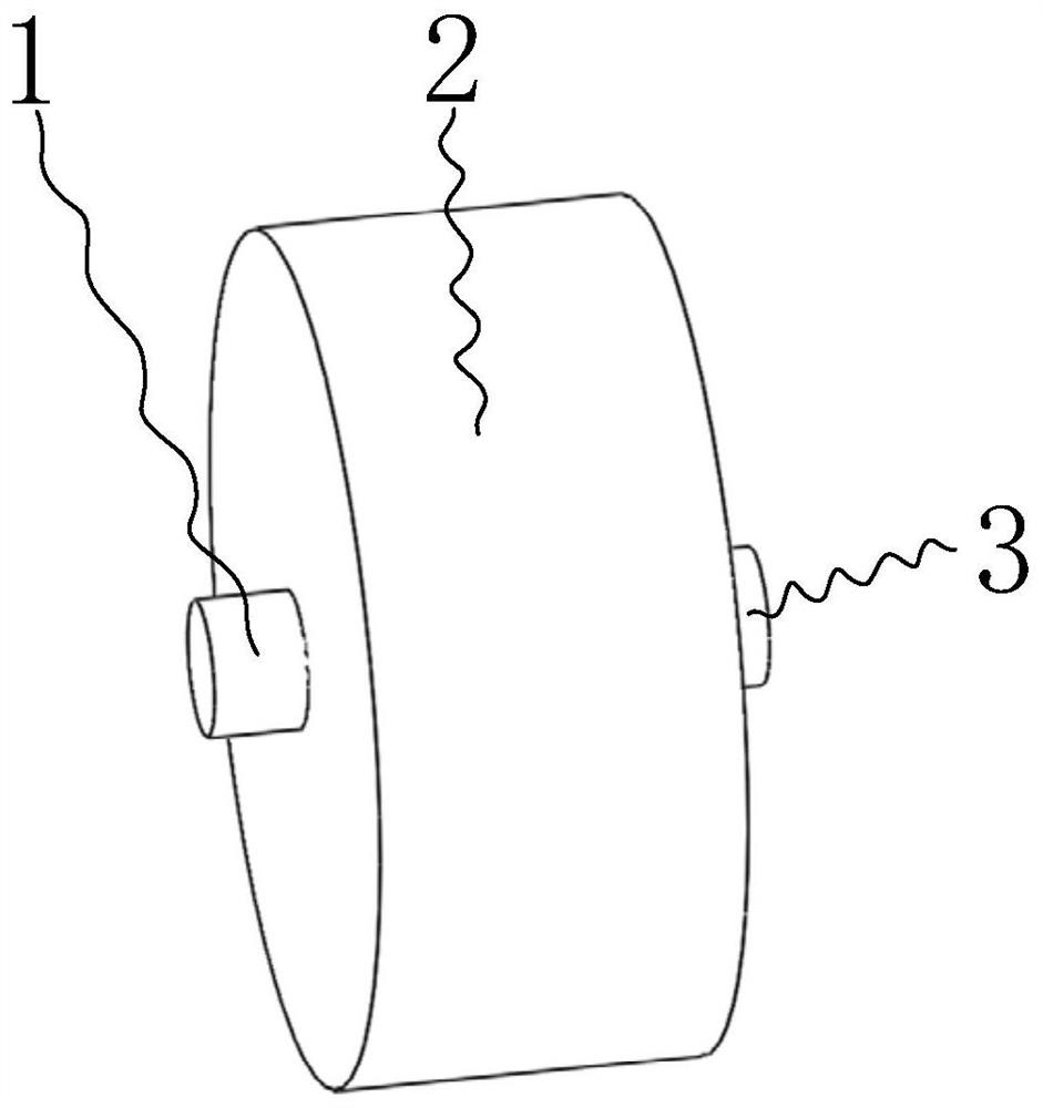
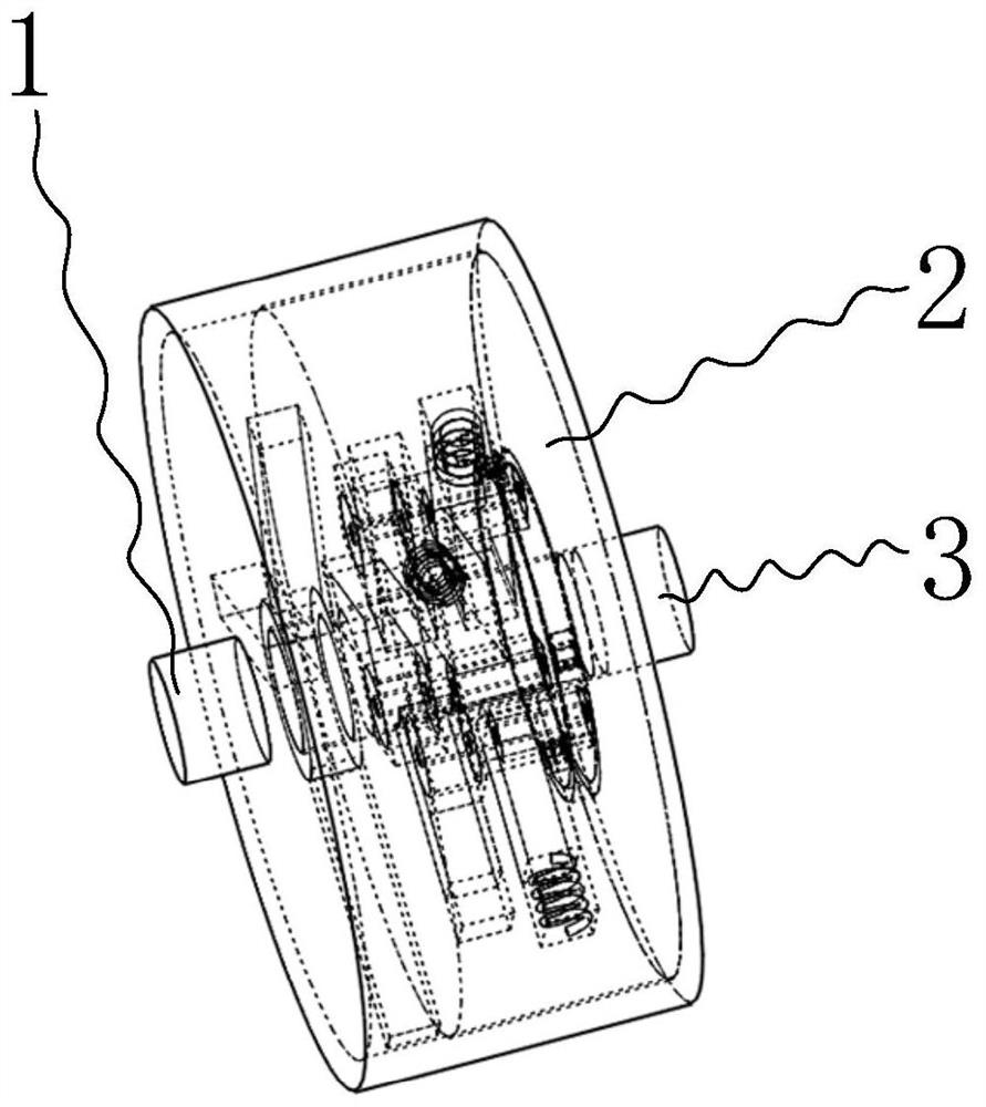
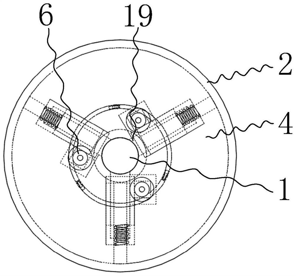
[0056]Specific implementation method: when using the transmission mechanism designed by the present invention, during normal use, the input shaft 3 will drive the installation shell 2 to rotate, and the rotation of the installation shell 2 will drive the drive cylinder 4 on which it is installed to rotate, and the rotation of the drive cylinder 4 will drive the three friction The block 19 rotates around the output shaft 1, and the three friction blocks 19 rotate around the output shaft 1 and will drive the output shaft 1 to rotate under the action of the friction pressure, that is, the input shaft 3 drives the output shaft 1 to rotate; After using for a long time, the three friction blocks 19 will be worn. In this state, since the first spring 10 is in the compression and pre-tightened state in the initial state, so under the pressure of the first spring 10 at this time, The adjustment block 20 will move downwards, and the downward movement of the adjustment block 20 will cause...


PUM


Abstract

The invention belongs to the technical field of transmission mechanism, and particularly relates to a transmission mechanism based on gear adjustment, which includes an output shaft, a mounting shell, an input shaft, a driving cylinder, and a friction block. The transmission mechanism designed by the invention is suitable for constant load and output speed For a certain mechanism, people can choose transmission mechanisms with different critical speeds according to the different needs of the mechanism. During the use of the transmission mechanism, power is transmitted between the input shaft and the output shaft through friction blocks, and between the friction blocks and the output shaft. Through friction transmission, and a pre-tightened first spring provides friction pressure between the friction block and the output shaft, preventing the output shaft from being stuck and burning out the drive motor; at the same time, through speed change, when the friction block is damaged to a certain extent Therefore, the first spring only needs to extend a small distance to make up for the wear of the friction block, so that the service life of the transmission mechanism becomes longer.

Description

[0001] Technical field [0002] The invention belongs to the technical field of transmission mechanisms, in particular to a transmission mechanism based on gear adjustment. Background technique [0003] The transmission mechanism is a component or mechanism that transmits power from one part of the machine to another, and makes the machine or machine parts move or operate. During the use of the traditional transmission mechanism, when the load on the output shaft is large or even stuck, the drive motor needs to pay a large driving force to drive or be stuck, and the drive motor may be stuck under long-term overload work Finally, it will cause internal overheating and burn it out; to solve the above load problem, we can design a transmission mechanism through friction transmission, which can allow the friction transmission to slip when the load is too large or the load exceeds the critical transmission torque of the friction transmission mechanism. Under normal circumstances, ...

Claims


Application Information

Patent Timeline
Patent Type & Authority Patents(China)
IPC IPC(8): F16H57/12
CPCF16H57/12F16H2057/127
Inventor 杨勇卢鹏李强孙丽洁
Owner NINGBO POWERNICE INTELLIGENT TECH CO LTD
Features
  • R&D
  • Intellectual Property
  • Life Sciences
  • Materials
  • Tech Scout
  • Unparalleled Data Quality
  • Higher Quality Content
  • 60% Fewer Hallucinations
Learn More