
Small electric power transmission support with bird repelling device

A power transmission and bird repelling technology, which is applied in the direction of cable suspension devices, electrical components, animal repellants, etc., can solve the problems of hidden safety hazards for installation workers, easy toppling of utility poles, and inconvenient installation, so as to ensure service life and effective Sequential efficient discharge, easy to use effect

Inactive Publication Date: 2018-12-04
蒙小东
View PDF0 Cites 1 Cited by
  • Summary
  • Abstract
  • Description
  • Claims
  • Application Information

AI Technical Summary

Problems solved by technology

[0002] As electricity occupies a more and more important position in people's lives, the number of utility poles is also increasing sharply, all over roads, fields and cities. Today's utility poles, especially low-voltage utility poles, are usually cylindrical It is made of cement, metal or other materials. Among them, cement and metal poles are heavier, have better wind resistance, are simple to manufacture, and are the most widely used. Because utility poles need to be used to erect wires, for example safety considerations, wires should be It is erected at a higher position, so the utility poles are made relatively slender. Although this saves materials, it also brings great inconvenience to the installation. When installing, ensure that the utility poles are vertical. Without fixed utility poles, it is easy to Toppled over, the heavy and slender utility poles have brought great hidden dangers to the safety of the installation workers. At the same time, the utility poles are vulnerable to the threat of lightning strikes because of their height. On the other hand, birds like to build nests on them. These all affect the The service life of the utility pole

Method used


Image

  • Small electric power transmission support with bird repelling device
  • Small electric power transmission support with bird repelling device

Examples


Embodiment Construction

[0014] The technical solution of this patent will be further described in detail below in conjunction with specific embodiments.

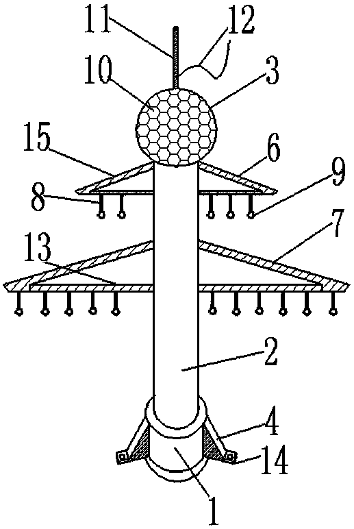
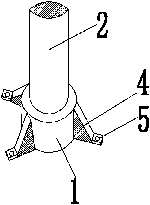
[0015] see Figure 1-2 , a small power transmission bracket with a bird repelling device, including a base 1, a rod body 2 and a reflective ball 3; the base 1 is provided with a fixed block 4; there are 3 fixed blocks 4, which are evenly distributed around the base 1 The fixed block 4 is provided with a bump 14; the bump 14 is provided with a threaded hole 5 for fixing; the top of the base 1 is connected with a rod body 2; the rod body 2 is provided with a short bracket 6 and a long bracket 7 The short bracket 6 and the long bracket 7 are made up of a cross bar 13 and a diagonal bar 15; the cross bar 13 is movably connected with the diagonal bar 15; the cross bar 13 is connected with several suspension wires 8; the suspension wire 8 is The insulating material with higher hardness; the wire fixing ring 9 is connected to the bottom of the suspension...


PUM


Abstract

The invention discloses a small electric power transmission support with a bird repelling device. The small electric power transmission support comprises a base, a rod body and a reflection ball, fixed blocks are arranged on the base, each fixed block is provided with a projection, the projection is provided with a threaded hole, the upper part of the base is connected with the rod body, the rod body is provided with a short support and a long support, the short support and the long support are formed by cross bars and diagonal rods, the cross bars are connected with a plurality of suspensionwires, the lower parts of the suspension wires are connected with wire fixing rings, the top end of the rod body is provided with the reflection ball, the reflection ball is provided with a pluralityof reflection lenses, the top end of the reflection ball is provided with a lightning rod, and the lightning rod is connected with a transmission line. According to the small electric power transmission support, the structure is simple, the operation is convenient, the bird repelling device is provided, the service lifetime of wire equipment is guaranteed, and the lightning rod arranged on the support can effectively prevent the support from being damaged by lightning strokes.

Description

technical field [0001] The invention relates to the field of power equipment, in particular to a small power transmission bracket with a bird repelling device. Background technique [0002] As electricity occupies a more and more important position in people's lives, the number of utility poles is also increasing sharply, all over roads, fields and cities. Today's utility poles, especially low-voltage utility poles, are usually cylindrical It is made of cement, metal or other materials. Among them, cement and metal poles are heavier, have better wind resistance, are simple to manufacture, and are the most widely used. Because utility poles need to be used to erect wires, for example safety considerations, wires should be It is erected at a higher position, so the utility poles are made relatively slender. Although this saves materials, it also brings great inconvenience to the installation. When installing, ensure that the utility poles are vertical. Without fixed utility po...

Claims


Application Information

Patent Timeline
Patent Type & Authority Applications(China)
IPC IPC(8): H02G7/05H02G13/00A01M29/10
CPCH02G7/05A01M29/10H02G13/40H02G13/80
Inventor 蒙小东
Owner 蒙小东
Learn More