Stamping die

A technology for stamping dies and dies, which is applied to forming tools, manufacturing tools, metal processing equipment, etc., can solve the problems of frequent replacement of dies, and achieve the effects of frequent replacement, high reliability and convenient use

Inactive Publication Date: 2018-12-07
许春燕
View PDF11 Cites 0 Cited by
  • Summary
  • Abstract
  • Description
  • Claims
  • Application Information

AI Technical Summary

Problems solved by technology

[0005] Beneficial effects of the present invention: a stamping die of the present invention, by adding a guide cone to realize the limit of the position of the top plate, thereby preventing the occurrence of the position deviation of the punch during the downward falling process, and the addition of the rubber pad Then the buffer between the top plate and the limit seat is realized. This design effectively prevents the hard contact between the top plate and the limit seat, and thus solves the problem of frequent replacement of the die to a certain extent. The addition of the telescopic spring will Realize the absorption of the kinetic energy of the top plate, this design effectively prevents the problem of noise generated by the contact between the limit seat and the top plate, and further improves the working environment of the staff. The invention is easy to use, easy to operate, good in stability and high in reliability

Method used


Image

  • Stamping die
  • Stamping die
  • Stamping die

Examples


Embodiment Construction

[0012] In order to make the technical means, creative features, goals and effects achieved by the present invention easy to understand, the present invention will be further described below in conjunction with specific embodiments.

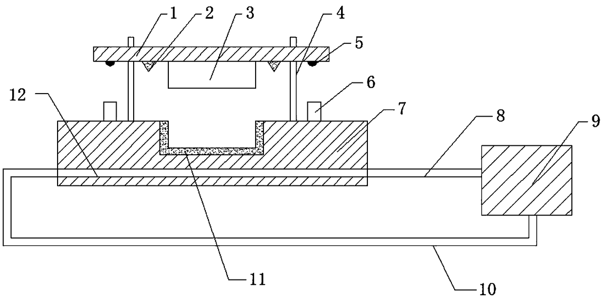
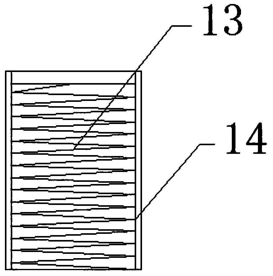
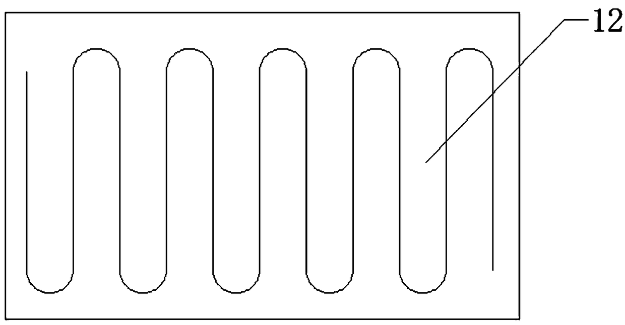
[0013] see figure 1 , figure 2 , image 3 and Figure 4 , the present invention provides a technical solution: a stamping die, including a stamping module main part, a limit device 6 and a cooling device, the stamping module main part consists of a top plate 1, a guide cone 2, a punch 3, a movable telescopic rod 4, a rubber Pad 5, limit seat 7 and die 11, the central axis of limit seat 7 is arranged perpendicular to the horizontal plane, the middle position of the upper end surface of limit seat 7 is equipped with die 11, and the limit device is installed around the die 11 6. The telescopic movable rod is arranged perpendicular to the lower end surface of the limit seat 7. The upper end of the telescopic movable rod is equipped with a top plat...


PUM


Abstract

The invention provides a stamping die. The central axis of a limiting base is arranged perpendicular to the horizontal plane, a female die is assembled in the middle of the upper end face of the limiting base, limiting devices are installed on the periphery of the female die, telescopic movable rods are arranged perpendicular to the lower end surface of the limiting base, a top plate is installedat the upper ends of the telescopic movable rods, and a male die is assembled at the middle position of the lower end face of the top plate. According to the stamping die, through the additional arrangement of guide cones, limiting of the position of the top plate is achieved, and then the situation that the position of the male die is deviated in the downward falling process is avoided; in addition, through the additional arrangement of rubber pads, buffering between the top plate and the limiting base is achieved, so that hard contact between the top plate and the limiting base is effectively prevented through the design; telescopic springs are additionally arranged so as to realize absorption of the kinetic energy of the top plate, so that the problem that the noise is generated due tothe fact that the limiting base is in contact with the top plate is effectively solved through the design, and the working environment of workers is improved; and the stamping die is convenient to use, convenient to operate, good in stability and high in reliability.

Description

technical field [0001] The invention relates to a stamping die, which belongs to the field of mechanical equipment. Background technique [0002] In the prior art, a stamping die is a special process equipment for processing materials into parts in cold stamping processing, called a cold stamping die. Stamping is a pressure processing method that uses a mold installed on a press to apply pressure to the material at room temperature to cause separation or plastic deformation to obtain the required parts. However, during the use of traditional stamping dies, the plate to be stamped often moves at the moment of stamping, which affects the effect of stamping, and after the traditional stamping dies are stamped on the plate, they often use manual or the punch itself The mechanical force makes the punch return the material. In this process, it will cause huge friction on the surface of the die, which seriously affects the service life of the die. Therefore, a stamping die is need...

Claims


Application Information

Patent Timeline
Patent Type & Authority Applications(China)
IPC IPC(8): B21D37/10B21D37/16
CPCB21D37/10B21D37/16
Inventor 不公告发明人
Owner 许春燕
Why Eureka
Try Eureka