


Quick Research
Generate reliable direction feasibility study reports for your R&D in just a few steps.

Technical Q&A
Discover and master advanced knowledge NOW. Basics, ideas, possibilities, all at once.

Find Solutions
As an expert in R&D theories, this can generate solutions to your technical problems instantly.

Evaluate Feasibility
Analyze your overall solution with one click, know your potential R&D risks in advance.

Monitor Landscape
Get weekly tech updates, stay abreast of the latest tech innovations and key insights.
Laser welding system suitable for online piece counting and working method thereof
A technology of laser welding and welding parts, applied in laser welding equipment, welding equipment, manufacturing tools, etc., can solve the problems of wasting labor costs, prone to errors, lack of online piece counting, etc., to improve the degree of automation and production efficiency, reduce human labor Dependency, the effect of improving statistical efficiency and accuracy
- Summary
- Abstract
- Description
- Claims
- Application Information
AI Technical Summary
Problems solved by technology
Method used
Image

Examples
Embodiment 1
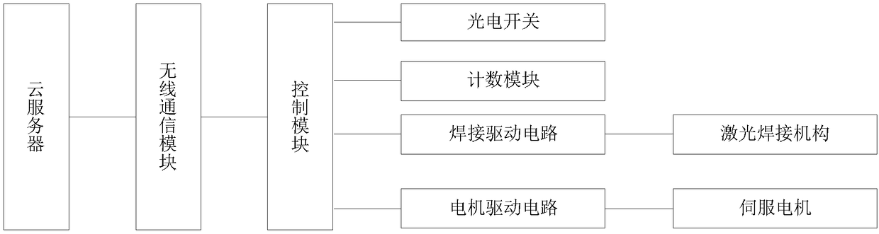
[0022] figure 1 It is a functional block diagram of the laser welding system of the present invention.
[0023] like figure 1 As shown, this embodiment 1 provides a laser welding system, including: a cloud server, a conveying line for conveying welded parts, a laser welding mechanism controlled and driven by a control module, and a counting module and a photoelectric welding mechanism respectively connected to the control module switch; the photoelectric switch is suitable for detecting the interval between adjacent welding pieces, so that the counting module counts the number of welding pieces; the control module is suitable for sending the number of welding pieces to the cloud server through the wireless communication module.
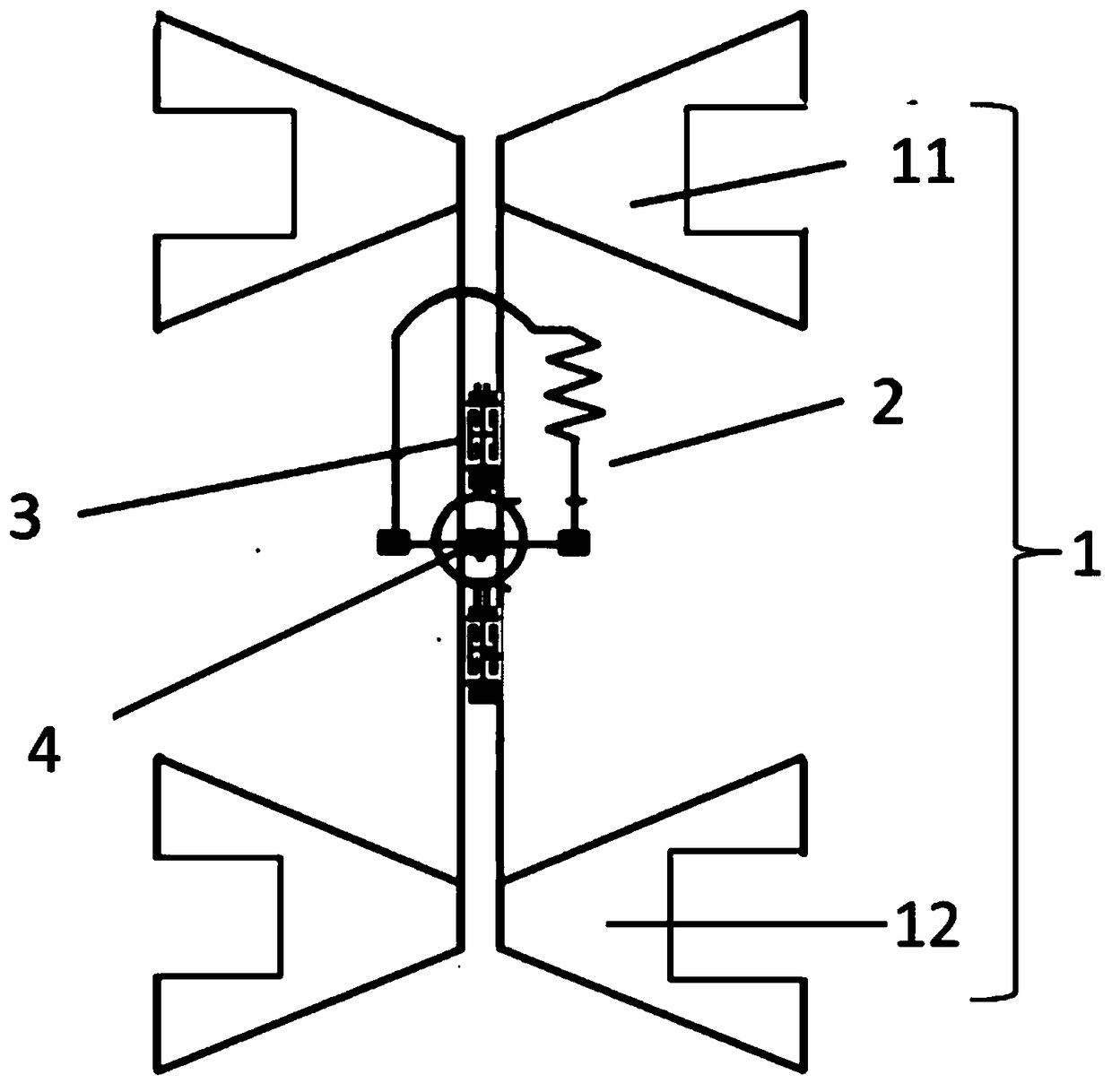
[0024] Optionally, the photoelectric switch, such as but not limited to E3F-20L / 20C1 type laser through-beam photoelectric switch sensor, is suitable for installation on both sides of the conveying line. The welded parts are suitable for being arran...
Embodiment 2
[0048] On the basis of Embodiment 1, this Embodiment 2 provides a working method of a laser welding system, the control module of the laser welding system is suitable for obtaining the quantity of welding parts online, and sending it to the cloud server through the wireless communication module, It can be used to monitor production efficiency or manually evaluate production progress.
[0049] For the specific structure and implementation process of the laser welding system, please refer to the relevant discussion of Embodiment 1, and details will not be repeated here.
PUM
| Property | Measurement | Unit |
|---|---|---|
| length | aaaaa | aaaaa |
| thickness | aaaaa | aaaaa |
| width | aaaaa | aaaaa |
Abstract
Description
Claims
Application Information
 - R&D Engineer
- R&D Manager
- IP Professional
- Industry Leading Data Capabilities
- Powerful AI technology
- Patent DNA Extraction
Browse by: Latest US Patents, China's latest patents, Technical Efficacy Thesaurus, Application Domain, Technology Topic, Popular Technical Reports.
© 2024 PatSnap. All rights reserved.Legal|Privacy policy|Modern Slavery Act Transparency Statement|Sitemap|About US| Contact US: help@patsnap.com