Locking Mechanism of Fiber Web Winding Machine

A fiber web and winder technology, applied in the direction of winding mechanism, winding strip, fiber processing, etc., can solve the problems of injury, uncontrollable movement, complex combination, etc., and achieve the effect of large clamping effect

Active Publication Date: 2021-02-26
TRUETZSCHLER GRP SE
View PDF7 Cites 0 Cited by
  • Summary
  • Abstract
  • Description
  • Claims
  • Application Information

AI Technical Summary

Problems solved by technology

[0003] For locking the winding shaft with the jaws, jaw arrangements are known which act on both sides with respect to the axis of rotation of the winding shaft, which are very complex in construction
In addition, the locking elements of such jaw arrangements have to approach the winding shaft from both sides, which complicates the combination of the movement path of the locking mechanism and the especially drive technology of the locking mechanism in the web winding machine.
In addition, with regard to energy losses, when the drive element actuates the jaws, it can result that the winding shaft, due to its weight, comes out of the locking mechanism and moves uncontrollably, for example falls.
This is a high risk of injury to persons located nearby and a risk of damage to other components such as the web winding machine

Method used


Image

  • Locking Mechanism of Fiber Web Winding Machine
  • Locking Mechanism of Fiber Web Winding Machine
  • Locking Mechanism of Fiber Web Winding Machine

Examples


Embodiment Construction

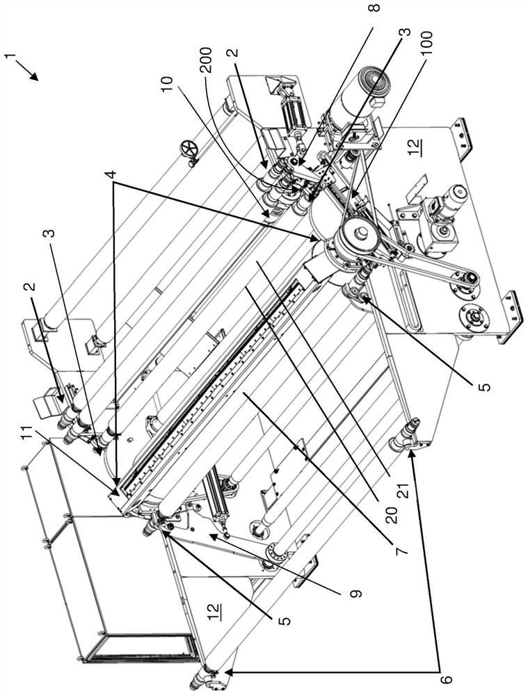
[0025] figure 1 A web winding machine 1 according to an embodiment of the invention is shown. Components that are not essential to the present invention will not be explained in detail.

[0026] The web winding machine 1 essentially comprises two frame walls 12 , which form a frame, which accommodates or holds all other functional components of the web winding machine 1 , via connecting bodies not shown.

[0027] In the area on the right, the machine frame wall 12 has a depository 2 in which unmarked winding shafts (here: two) are located.

[0028] The web winder 1 also comprises a recess on each frame wall 12 defining a waiting position 3 for the winding shaft 20 . Since the winding shaft is held on both sides by the frame walls 12 , the waiting position 3 is realized with two frame walls 12 . The machine frame wall 12 thus forms, with the waiting position 3 , a holding section for the winding shaft 20 to be wound.

[0029] In the waiting position 3, the winding shaft 20 ...


PUM


Abstract

Device (200), which is set up for integration into a fiber web winding machine, whereby the winding shaft (20) is transferred from the waiting position (3) to the unwinding position (4) and / or the lapping position by means of said device (5). The device has a lever arrangement which in the locked state surrounds the winding shaft from one side in such a way that the lever arrangement, viewed in the longitudinal direction of the winding shaft, is open towards one side of the winding shaft, and the lever is arranged such that The force that prevents the weight of the winding shaft from being used to cancel the latch is introduced into the lever arrangement. A web winder (1) configured to wind the incoming web with the first winding shaft and to bring the second winding shaft to a waiting position. It has the means described above. In the waiting state, the device is placed on the conveyor section in such a way that the lever arrangement grips the second winding shaft in a clamping manner. The transport section is designed to move the clamped second winding shaft from the waiting position towards the unwinding position and / or the winding position.

Description

technical field [0001] The present invention relates to a locking mechanism for a web winding machine for securely clamping a winding shaft and to a web winding machine equipped with such a locking mechanism. Background technique [0002] Fiber web winders are known per se. They are used for winding fiber webs, for example from cards, on winding shafts. For this purpose, the empty winding shafts are wound one after the other in an automatic exchange. This is accomplished by directing the incoming web material around rotating contact rolls. An empty winding shaft provided with an adhesive surface and rotating in the opposite direction to the touch roll rests against the touch roll and receives the fiber web from the touch roll due to adhesion. Empty winding shafts are generally accommodated in the depository of the fiber web winding machine. In order to wind the empty winding shaft, it is transferred from the storage place into a waiting position, in which the winding sha...

Claims


Application Information

Patent Timeline
Patent Type & Authority Patents(China)
IPC IPC(8): B65H18/10
CPCB65H18/10B25J15/022B65H18/028B65H18/16B65H19/2261B65H19/305B65H2301/41822B65H2701/174D01G27/04
Inventor 克吕斯托夫·巴尔洛克安德烈亚斯·哈赫曼
Owner TRUETZSCHLER GRP SE
Why Eureka
Try Eureka