A gantry for particle therapy as an arm rotating in the longitudinal plane

A rack and therapy technology, applied in X-ray/γ-ray/particle irradiation therapy, radiotherapy, treatment, etc., can solve problems such as large space, and achieve the effect of simple mechanical configuration

Active Publication Date: 2019-04-02
PAUL SCHERRER INSTITUT
View PDF7 Cites 4 Cited by
  • Summary
  • Abstract
  • Description
  • Claims
  • Application Information

AI Technical Summary

Problems solved by technology

However, these racks in the form of C-arms require considerable space to allow rotation involving systems weighing 10 tons

Method used


Image

  • A gantry for particle therapy as an arm rotating in the longitudinal plane
  • A gantry for particle therapy as an arm rotating in the longitudinal plane
  • A gantry for particle therapy as an arm rotating in the longitudinal plane

Examples


Embodiment Construction

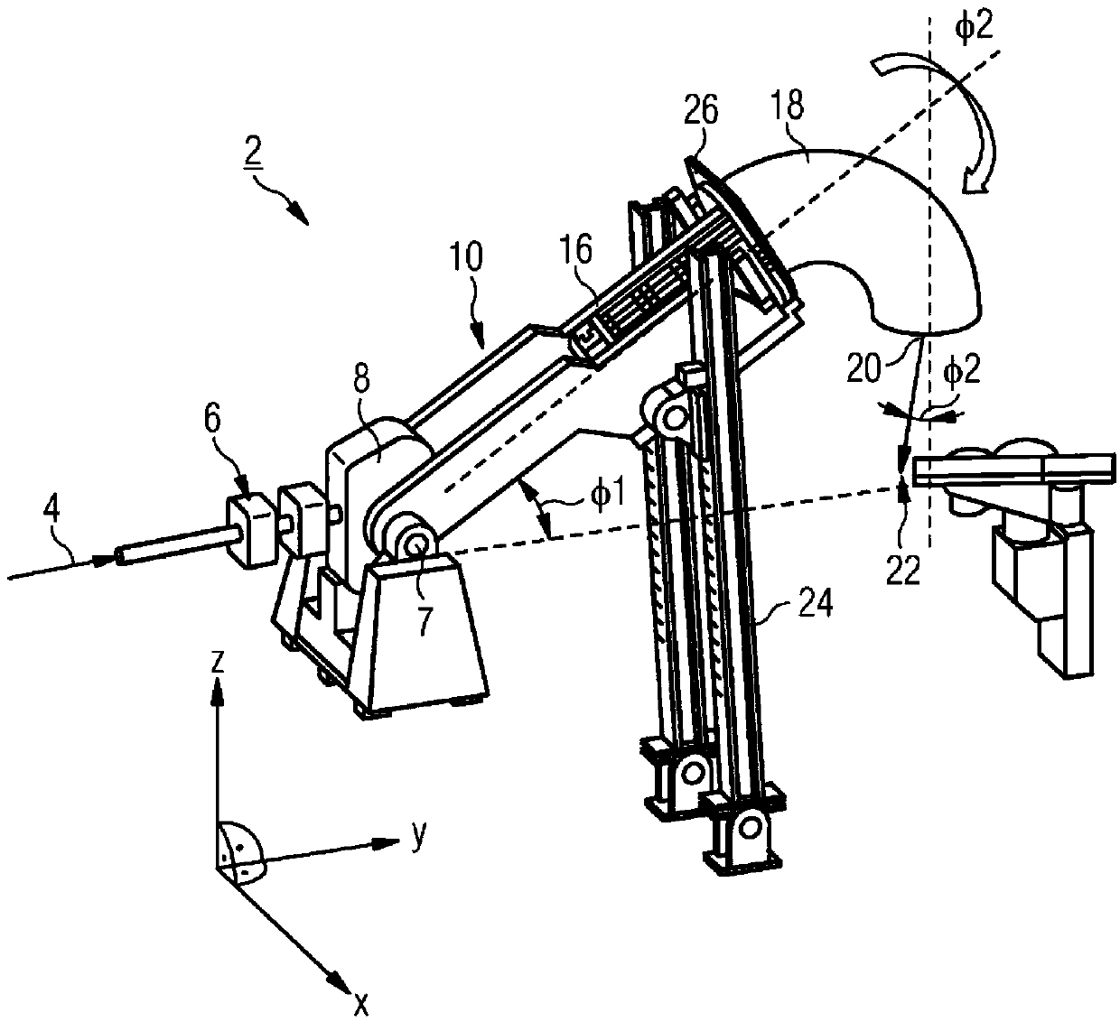
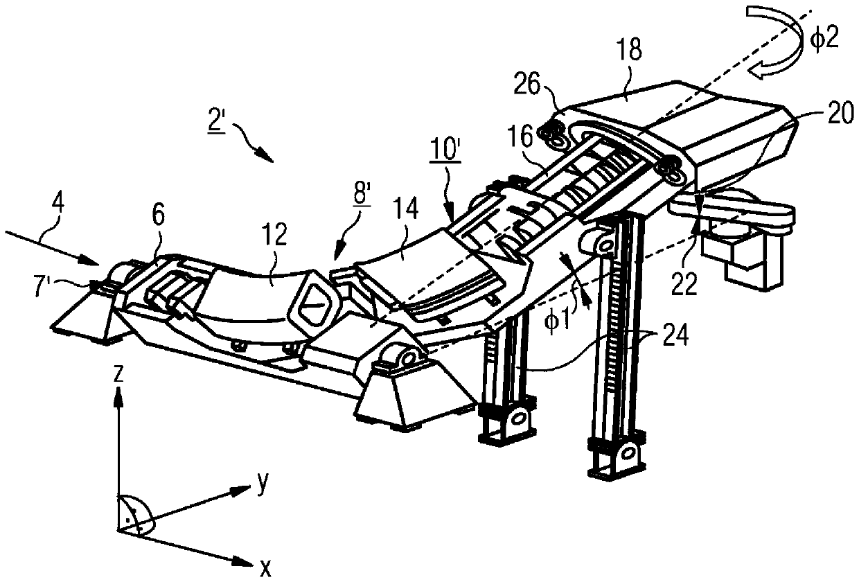
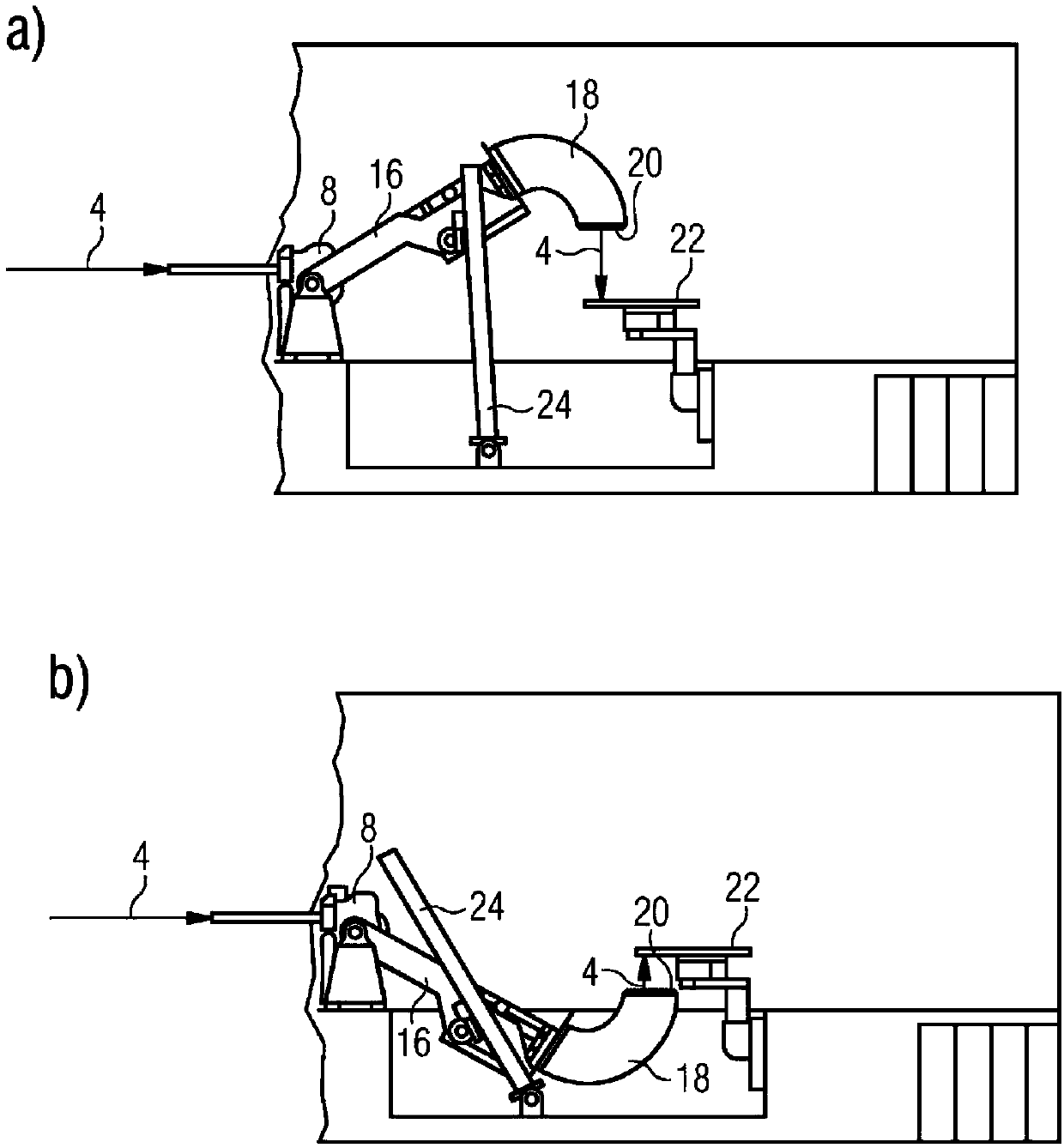
[0033] figure 1 A first system 2 for particle beam therapy delivery is schematically shown. The system 2 comprises a beam coupling section 6 for the incident particle beam 4 followed by a first bending section 8 . In this example, the frame 10 is supported by a tilt mechanism 24 that allows the frame 10 to tilt vertically (along the z-axis) by a first angle Φ 1 , Φ 1 ∈[-90°; +90°], wherein the frame 10 includes a bearing (pivot) 7, which is arranged at the entrance of the beam coupling part 6, so that the entire frame 10 Can be tilted in the z direction. The first bending portion 8 bends the particle beam 4 such as the proton beam or the ion beam in the vertical yz plane by an angle Φ 1 .

[0034] Furthermore, the second curved portion 18 and the beam nozzle 20 can be rotated by a rotation mechanism 26 arranged so that the second curved portion 18 and the beam nozzle 20 can rotate around the angle Φ 1 The orientation rotation angle Φ given by 2 , where Φ 2 ∈[-180°; +18...


PUM


Abstract

The present invention discloses a system (2, 2') for particle beam therapy, comprising as seen in the flow direction of the particle beam (4): a) an adjustable gantry (10, 10') for the beam delivery to a target volume, said gantry comprising: a1) a beam coupling section (6) for the incoming particle beam (4); said incoming particle beam (4) being oriented substantially horizontally thereby defining a horizontal plane; a2) a first beam bending section (8, 8') comprising a number of beam deflection and/or focusing magnets (12, 14) wherein the first bending section (8, 8') either bends the particle beam (4) with an adjustable angle into the vertical plane, or with 90 degrees in the horizontal plane, but with the mechanical possibility to rotate with an adjustable angle along the axis of the incoming particle beam (4); a3) a beam transport section (16) receiving the particle beam (4) leaving the first beam bending section (8, 8') and guiding the particle beam (4) to a second beam bending section (18); a4) the second beam bending section (18) comprising a number of beam deflection magnets and/or beam focusing magnets; a5) a beam nozzle (20) comprising a window for the exit of the particle beam (4); and b) a patient table/chair (22) being rotatable in the horizontal plane or in a plane being parallel to the horizontal plane and optionally being adjustable vertically, wherein: c) thegantry (10, 10') is supported by a tilting mechanism (24) allowing the gantry (10, 10') to be tilted vertically by an angle [Phi]1 , [Phi]1 belongs to [-90 degrees; +90 degrees], wherein the gantry (10, 10') comprises a pivot (7, 7') being disposed in the region of the first bending section (8, 8'); and d) a rotation mechanism (26) being disposed in a way that the second beam bending section (18)and the beam nozzle (20) being rotatable by an angle [Phi]2 , [Phi]2 belongs to [-180 degrees; +180 degrees] around a direction given by the angle [phi] 1 .

Description

technical field [0001] The invention relates to a rack for particles. Background technique [0002] A gantry is commonly used in proton therapy and ion therapy to direct the incident beam at an optimal angle to a target (usually a tumor) in a patient. A gantry is a beam delivery system (usually including magnets) mounted on a mechanical structure that is able to surround a patient positioned at a treatment position - usually lying but in some cases also seated on a dedicated treatment couch / Chair - swivel. Typically, the angle of rotation of the gantry is slightly greater than 360 degrees, but slightly greater than 180 degrees are also used in some gantry to save space and allow access to the treatment couch / chair at any time during treatment. An example of a typical rotatable gantry used for proton therapy is disclosed in European Patent Application 15194 795.9 and in International Patent Application WO 2013 / 149945 Al. [0003] For various gantry orientations, the rotat...

Claims


Application Information

Patent Timeline
Patent Type & Authority Applications(China)
IPC IPC(8): A61N5/10G21K5/10
CPCA61N5/1081G21K5/10A61N2005/1087A61N5/1082A61N5/1028A61N5/1031
Inventor 雅各布斯·马尔滕·席佩斯亚历山大·格贝尔斯哈根
Owner PAUL SCHERRER INSTITUT
Why Eureka
Try Eureka