Conveying device
A technology of conveying device and conveying track, applied in the direction of lifting device, electromechanical device, transportation and packaging, etc., can solve problems such as damaged items and equipment, stuck items being conveyed, hidden safety hazards, etc.
- Summary
- Abstract
- Description
- Claims
- Application Information
AI Technical Summary
Problems solved by technology
Method used
Image

Examples
Embodiment Construction
[0020] Through the description of the embodiments below, the specific implementation of the present invention includes the shape, structure, mutual position and connection relationship between the various parts, the function and working principle of each part, the manufacturing process and the operation and use method of the various components involved. etc., to make further detailed descriptions to help those skilled in the art have a more complete, accurate and in-depth understanding of the inventive concepts and technical solutions of the present invention.
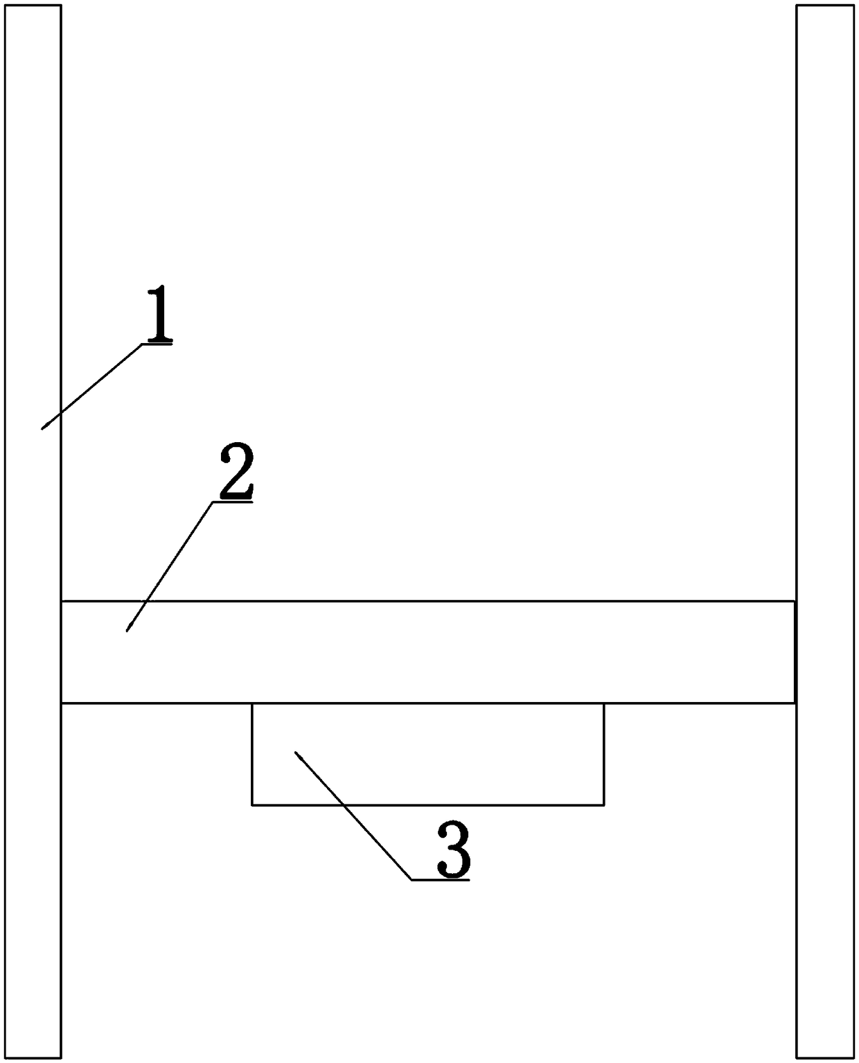
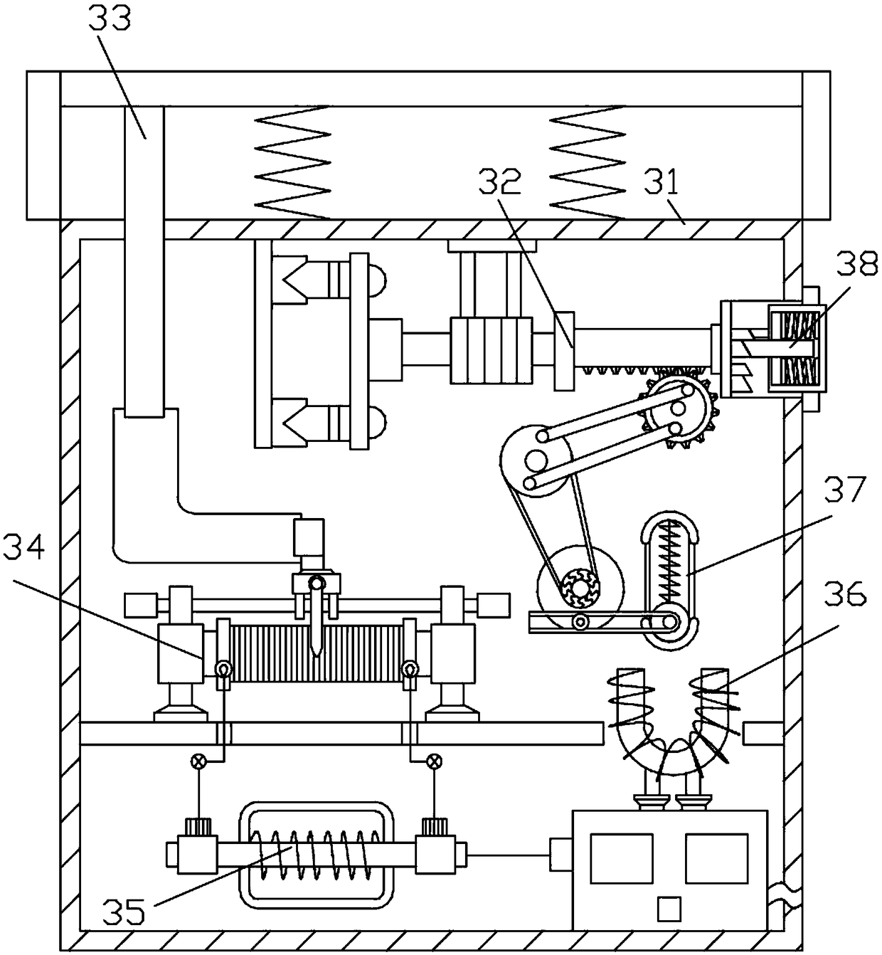
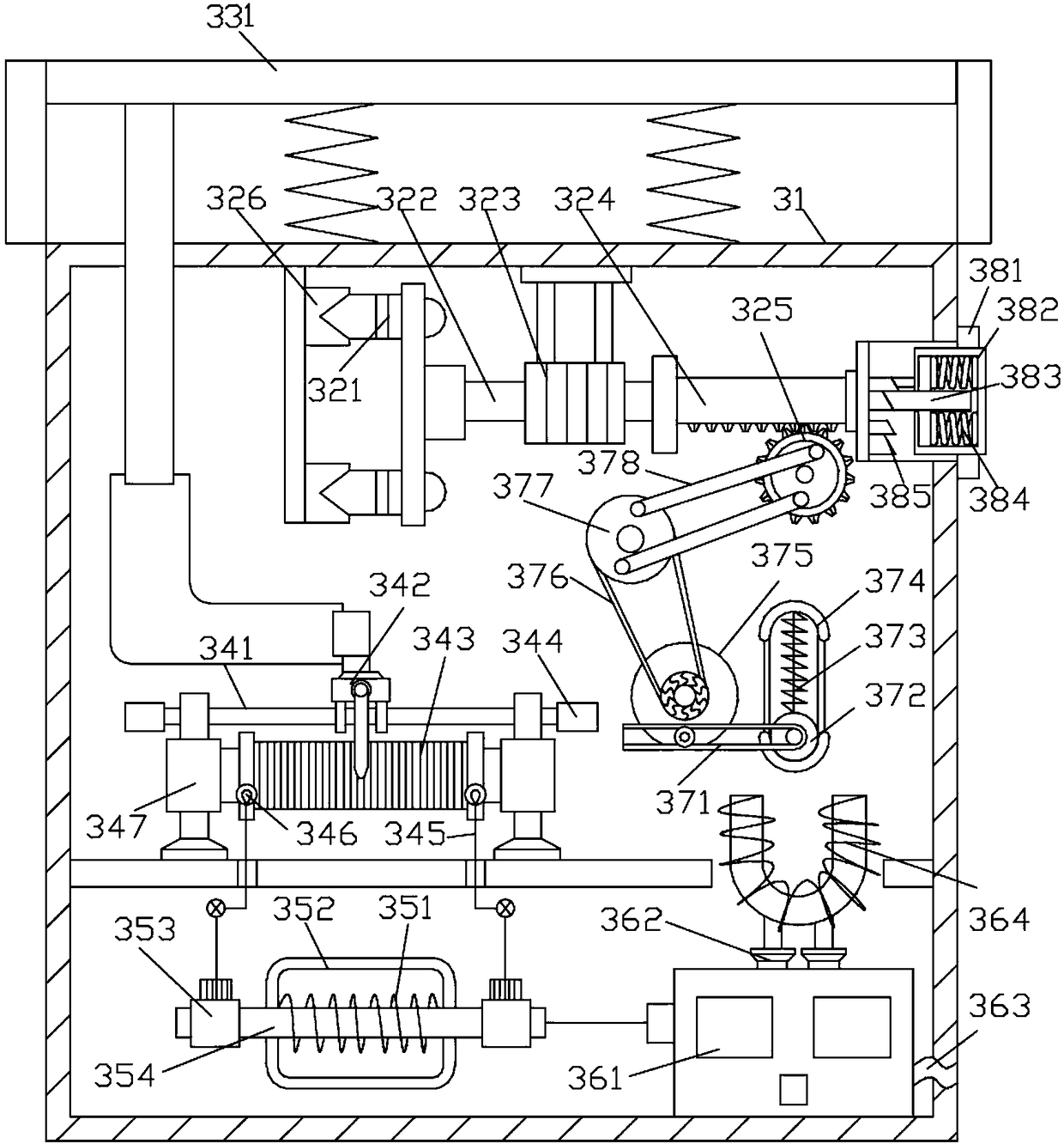
[0021] A conveying device, comprising a conveying track 1, a placing platform 2 is movable installed in the conveying track 1, the placing platform 2 can move up and down along the conveying track 1, the placing platform 2 is connected with a conveying motor that drives the placing platform 2 to move, and the placing platform 2 is placed under the A safety device 3 is also installed, and the safety device 3 is electrica...
PUM
 Abstract
Description
Claims
Application Information