Steel belt elevator

A steel belt and elevator technology, applied in the field of elevator equipment, can solve problems such as the influence of guide rail installation cycle, high installation difficulty, inaccurate installation positioning, etc., and achieve the effect of low elevator building shaft requirements, shortening installation time, and reducing connection structure.

Inactive Publication Date: 2018-12-07
佛山菱王科技有限公司
View PDF5 Cites 2 Cited by
  • Summary
  • Abstract
  • Description
  • Claims
  • Application Information

AI Technical Summary

Problems solved by technology

However, this product is rarely used in the market at present, so the experience in the design and installation of elevator components is still relatively lacking, and there are high requirements for the elevator building shaft. Because the structure of the steel belt elevator is different from the previous vertical elevator There is a big difference. In order to save space and reduce loss, when installing various components in the hoistway, considering factors such as space and cost, the elevator components are usually installed on the reserved mounting steel inside the hoistway, and other elevator rope head plate devices After the installation is completed, the wall needs to be filled, which not only increases the user's installation cost but also increases the user's maintenance cost, and the connection and installation of each component is complicated, which affects the normal installation cycle of the guide rail. Inaccurate installation positioning, high installation difficulty, unsatisfactory guiding stability, easy wear, easy misalignment and other problems cause the steel belt to slip or even fall off, affecting the overall service life of the elevator

Method used


Image

  • Steel belt elevator
  • Steel belt elevator
  • Steel belt elevator

Examples


Embodiment Construction

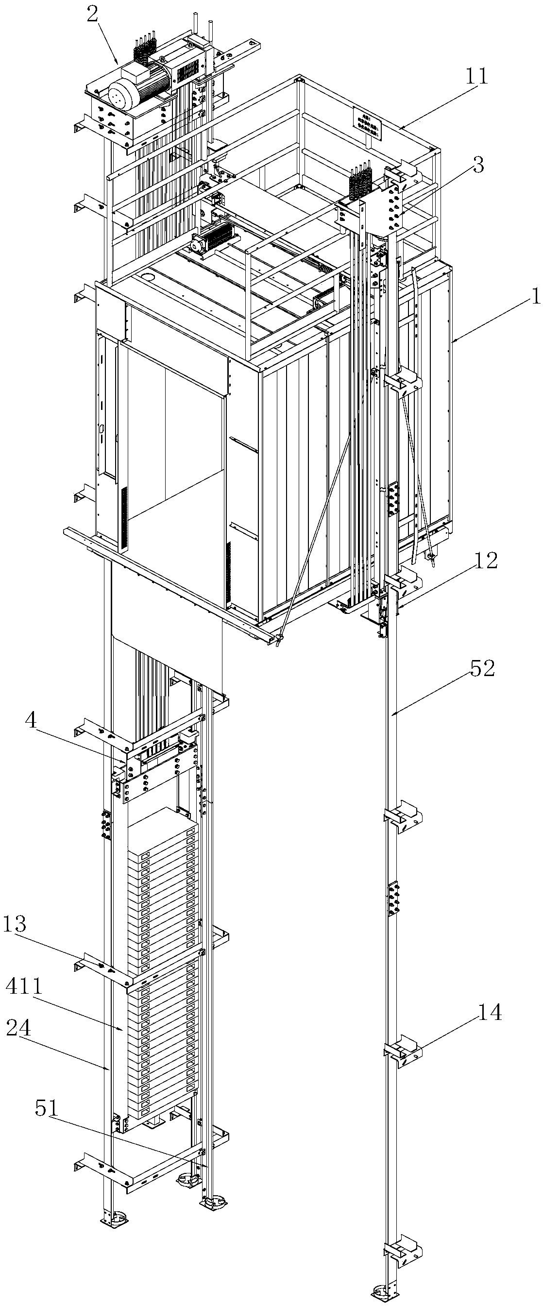
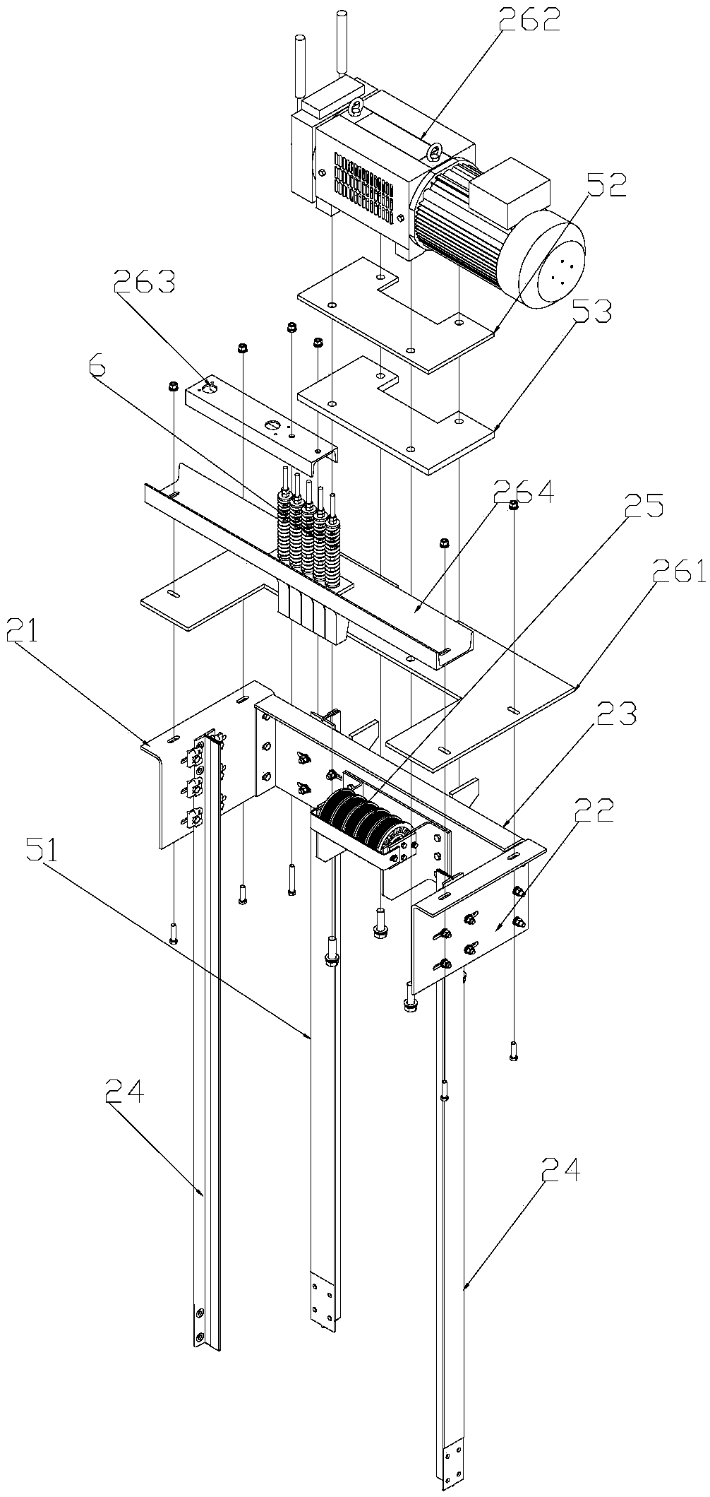
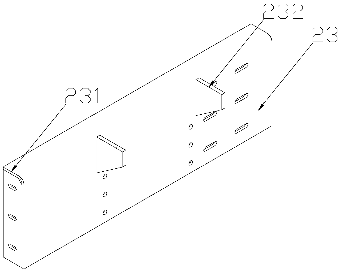
[0023] Such as Figure 1-Figure 4 As shown, the steel belt elevator described in this embodiment includes an elevator car 1 and a load-bearing device 2 used in conjunction with the elevator car 1, a rope head device 3, and a counterweight device 4. The top of the elevator car 1 is provided with The safety guardrail 11 of the side opening of the car door, the upper left and right sides of the safety guardrail 11 on the elevator car 1 are respectively provided with a load-bearing device 2 for carrying the weight of the elevator car and a rope end device 3 for fixing the elevator driving steel belt, The elevator car 1 is provided with a safety tongs 12 used in conjunction with the car guide rails, a counterweight device 4 for balancing the weight of the car is provided below the load-bearing device 2, and the load-bearing device 2 is formed by the first side plate 21 and the second side plate 22 are composed of a bolt structure clamping connecting plate 23, the outer surface of t...


PUM


Abstract

The invention belongs to the technical field of elevator equipment, and particularly relates to a steel belt elevator. The elevator comprises an elevator car, a bearing device, a rope head device anda counterweight device, wherein the bearing device, the rope head device and the counterweight device are used in cooperation with the elevator car, a safety fence opened on a car door side is arranged on the top of the elevator car, the bearing device used for bearing the weight of the elevator car and the rope device for fixing an elevator transmission steel belt are arranged on the two sides ofa mounting hoistway of the elevator car, the elevator car is provided with a safety clamp used in cooperation with a speed limiter and a guide rail, and the counterweight device for balancing the weight of the car is arranged below the bearing device. The bearing device, the rope head device and the counterweight device does not need to generate structural relation, except for transmission, withother external parts, the connecting structure is reduced, meanwhile, the use stability is improved, mounting is convenient, the requirement for the elevator building shaft is low, the elevator can bewidely applied to steel belt elevator products, and the considerable economic value is generated.

Description

technical field [0001] The invention belongs to the technical field of elevator equipment, in particular to a steel belt elevator. Background technique [0002] In recent years, with the development of elevator technology, the steel wire rope of the elevator traction drive has also evolved into a steel belt drive, and its life is 2-3 times that of the traditional steel wire rope; the weight is lighter, about 20% lighter than the traditional steel wire rope; it is more durable , stronger security, which gives passengers a safety factor of at least 12; can effectively reduce vibration and noise. However, this product is rarely used in the market at present, so the experience in the design and installation of elevator components is still relatively lacking, and there are high requirements for the elevator building shaft. Because the structure of the steel belt elevator is different from the previous vertical elevator There is a big difference. In order to save space and reduce...

Claims


Application Information

Patent Timeline
Patent Type & Authority Applications(China)
IPC IPC(8): B66B11/02
CPCB66B11/0226
Inventor 刘伟东蒋乐朱明明韦猛健
Owner 佛山菱王科技有限公司
Why Eureka
Try Eureka