Liquid gas storage tank decompression leakage safety valve and using method thereof

A technology of liquefied gas tank and safety valve, applied in the direction of safety valve, balance valve, valve device, etc., can solve the problems of unreliable operation of safety valve, inability to automatically close the valve, explosion loss, etc., to avoid explosion and personnel poisoning, Stable and reliable valve operation and significant social benefits

Pending Publication Date: 2018-12-07
TIANJIN FIRE RES INST +1
View PDF8 Cites 1 Cited by
  • Summary
  • Abstract
  • Description
  • Claims
  • Application Information

AI Technical Summary

Problems solved by technology

However, liquefied gas is flammable and explosive, so the hazards are mainly reflected in two aspects: 1. Leakage of liquefied gas before a fire may cause poisoning and explosion hazards
2. After a fire, the leakage of liquefied gas causes combustion and explosion, resulting in increased losses
[0005] The liquefied gas tank decompression safety valve solves the problem of burning and explosion caused by the leakage of liquefied gas when a fire breaks out.
[0006] However, there are still some deficiencies in the decompression safety valve of the liquefied gas tank. When the liquefied gas tank leaks, the valve cannot be automatically closed, and the safety of explosion or gas poisoning due to the liquefied gas tank leakage cannot be solved. Hidden problems
At the same time, the connection between the sealing cap and the valve stem of the liquefied gas tank decompression safety valve is not reliable enough, and it may fall off during actual use, which makes the work of the safety valve not reliable enough

Method used


Image

  • Liquid gas storage tank decompression leakage safety valve and using method thereof
  • Liquid gas storage tank decompression leakage safety valve and using method thereof
  • Liquid gas storage tank decompression leakage safety valve and using method thereof

Examples


Embodiment Construction

[0030] The present invention will be further described below in conjunction with the accompanying drawings and embodiments.

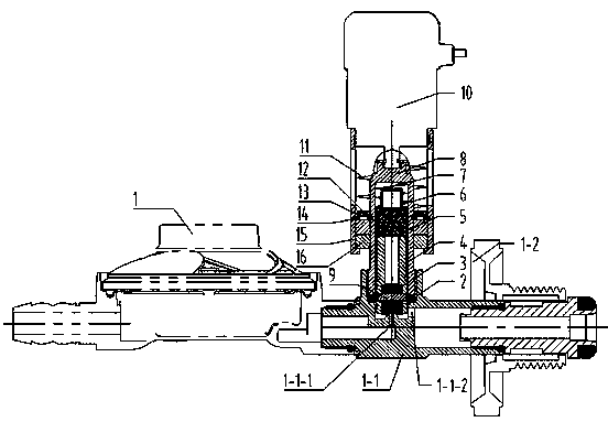
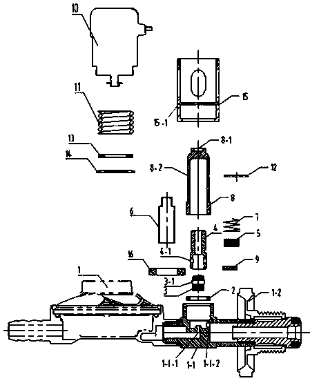
[0031] Such as Figure 1 to Figure 4 As shown, a liquefied gas tank decompression leakage safety valve includes a valve body 1, a gasket 2, a sealing cap 3, a valve stem 4, a magnetic core 5, a magnetic core sleeve 6, a small spring 7, a sealing sleeve 8, a temperature sensing Element 11, small circlip 12, gasket 13, large circlip 14, valve cover 15, magnetic ring 16, small valve body 1-1, handwheel connector 1-2 also include stainless steel pin 9, electromagnet 10.

[0032] The sealing cap 3 is a cylinder, and the middle position of the sealing cap 3 is horizontally provided with a pin hole I3-1.

[0033] The valve rod 4 is cylindrical, and a pin hole II4-1 is horizontally provided on the wall of the lower end of the valve rod 4 .

[0034] The sealing sleeve 8 is barrel-shaped, and a circular pit 8-1 is arranged on the upper end surface of the sealin...


PUM


Abstract

The invention relates to a liquid gas storage tank decompression leakage safety valve and a using method thereof. When the environment temperature rises to reach the temperature set by a temperature-sensing element, the temperature-sensing element extends to enable a valve cover and two magnet rings to move upwards wholly, the two magnet rings and two upward repulsive forces to magnetic cores become downward repulsive forces to the magnetic cores, small springs are released, magnetic core sleeves are forced to downwards do axial motion, an air outlet hole I of a small valve body is plugged through a sealing cap, and supply of liquid gas is cut off; when fuel gas leaks, an electromagnet receives a driving source, a static iron core and a movable iron core generate attraction force, and thestatic iron core drives the valve cover to wholly and upwards do axial motion; and in the upward motion process of the valve cover and the two magnet rings, the two magnet rings and the two upward repulsive forces to the magnetic cores become downward repulsive forces to the magnetic cores, the small spring is released, the magnetic core sleeves are forced to downwards move, the air outlet hole Iof the small valve body is plugged through the sealing cap, and supply of the liquid gas is cut off. Dangers of explosion and person poisoning generated by liquid gas leakage are avoided.

Description

technical field [0001] The invention relates to a liquefied gas tank decompression leakage safety valve and its use method. When the liquefied gas tank is in use and the ambient temperature is too high, the liquefied gas can be cut off automatically, and it can also be closed electrically when the leakage concentration of the liquefied gas reaches a set value. The valve can also be closed manually. Background technique [0002] Liquefied gas tanks are currently widely used in urban and rural residential buildings, some enterprises and institutions, and kitchens in the catering industry. However, liquefied gas is flammable and explosive, so the hazards are mainly reflected in two aspects: 1. The leakage of liquefied gas before a fire may cause poisoning and explosion hazards. 2. After a fire occurs, the leakage of liquefied gas causes combustion and explosion, resulting in increased losses. During the use of liquefied gas, leakage accidents of liquefied gas occur frequently...

Claims


Application Information

Patent Timeline
Patent Type & Authority Applications(China)
IPC IPC(8): F16K17/38F16K17/36
CPCF16K17/36F16K17/38
Inventor 许晓元刘晅亚张清海沈俊清薛浩纪超
Owner TIANJIN FIRE RES INST
Why Eureka
Try Eureka