
Pan capable of preventing oil smoke overflow

A technology for preventing oil fume and overflowing pot, applied in the field of daily life, can solve problems such as easy spillage of oil fume, achieve good market prospects, improve kitchen sanitation environment, and have the effects of great practicability

Inactive Publication Date: 2018-12-07
福州卫康智能科技有限公司
View PDF6 Cites 0 Cited by
  • Summary
  • Abstract
  • Description
  • Claims
  • Application Information

AI Technical Summary

Problems solved by technology

[0003] The purpose of the present invention is to provide an oil fume prevention pot, which can effectively solve the problem that the oil fume in the pot is easy to overflow

Method used


Image

  • Pan capable of preventing oil smoke overflow
  • Pan capable of preventing oil smoke overflow
  • Pan capable of preventing oil smoke overflow

Examples


Embodiment 1

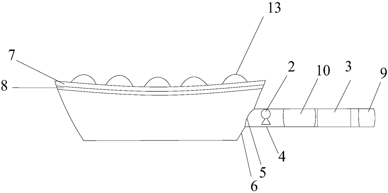
[0021] Such as figure 1 As shown, the present invention discloses an oil fume prevention pot, which is composed of a pot body and a handle. The upper end of the pot body is provided with a ventilation pipe 1, and the ventilation pipe 1 is provided with an air guide port communicating with the outside world. The opening of the air guide port is upward to allow ventilation The pipe 1 includes an upper half-pipe 7 and a lower half-pipe 8 , the upper half-pipe 7 and the lower half-pipe 8 are engaged to form a ventilation pipe 1 , and the air guide is located on the upper half-pipe 7 . Because the upper half-pipe and the lower half-pipe are snap-fit ​​connected, the upper half-pipe and the lower half-pipe can be disassembled and separated, and the oil stain in the ventilation pipe can be cleaned conveniently. The inside of the handle is provided with a fan 2 and a battery 3 for providing electric energy for the fan 2 , and a heat insulating layer 10 is provided between the fan 2 an...

Embodiment 2

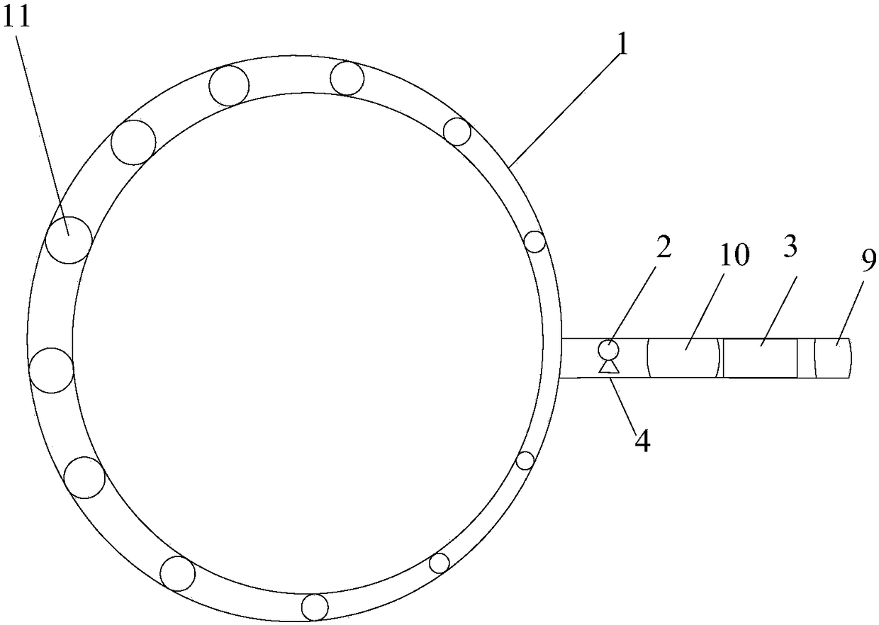
[0024] Such as figure 2 As shown, the difference between Embodiment 2 and Embodiment 1 is that: the air guide opening is composed of several air guide holes 11 , and the air guide holes 11 are arranged along the length direction of the ventilation pipe 1 . The farther the distance between the air guide hole 11 and the air outlet 5 is, the larger the diameter of the air guide hole 11 is. This is because the closer the air guide hole 11 is to the fan 2, the greater the flow velocity of the air coming out of the air guide hole 11, and the greater the driving force of the air with a higher flow rate to push the oil fume upward. Force remains equal. The farther the distance between the air guide hole 11 and the air outlet 5 is, the larger the diameter of the air guide hole 11 is.

Embodiment 3

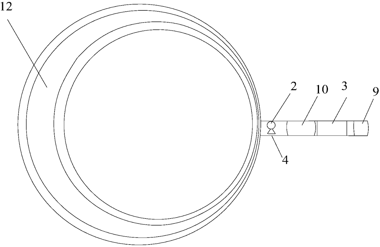
[0026] Such as image 3 As shown, the difference between Embodiment 3 and Embodiment 1 is that: the ventilation pipe 1 is provided with an air guide groove 12 along its length direction, and the air guide groove 12 forms an air guide opening. The farther the distance between the air guide groove 12 and the air outlet 5 is, the larger the opening of the air guide groove 12 is, and the principle is consistent with that of embodiment 2.


PUM


Abstract

The invention discloses a pan capable of preventing oil smoke overflow. The pan capable of preventing oil smoke overflow is composed of a pan body and a handle; the upper end of the pan body is provided with a ventilation duct; the ventilation duct is provided with a wind guiding port communicated with the outside; the opening of the wind guiding port is designed to be upward; a blower fan and a battery used for providing the blower fan with electricity energy are arranged in the handle; the handle is provided with a gas inlet and a gas outlet which are designed to match the blower fan; the gas outlet is communicated with the ventilation duct. The pan is capable of realizing gathering of oil smoke in the pan toward the center of the pan body, solving a problem in the prior art that overflow of oil smoke in the pan is easily caused preferably, increasing smoke ventilator oil smoke absorption working efficiency, and improving kitchen environment, is convenient to use, is high in practicality, and is promising in market prospect.

Description

technical field [0001] The invention relates to the field of daily life, in particular to an oil fume preventing pan. Background technique [0002] Pot is an indispensable item in people's daily life. With the improvement of living standards, people have higher and higher requirements for the kitchen sanitation environment. When people cook in the kitchen, oil will produce oily smoke when heated. The hot steam inside will drift randomly, affecting our breathing and threatening our health. On the other hand, because the distance between the pot and the range hood is too far or the range hood is aging, the suction of the range hood is not strong, even when the range hood is turned on. Under this condition, the oily fume emitted from the pot is easy to overflow and cannot be completely sucked away, threatening our health. Contents of the invention [0003] The object of the present invention is to provide a cooking fume prevention pot, which can effectively solve the problem...

Claims


Application Information

Patent Timeline
Patent Type & Authority Applications(China)
IPC IPC(8): F24C15/20A47J27/00
CPCA47J27/002F24C15/20
Inventor 王一强姜日忠
Owner 福州卫康智能科技有限公司
Learn More