Testing device for abrasion resistance of automobile tire

A technology for automobile tires and testing devices, which is used in automobile tire testing, measuring devices, and testing wear resistance, etc., can solve the problems of inconvenient observation and high labor intensity, and achieve the improvement of testing effect, reduction of labor intensity, and convenient observation. Effect

Active Publication Date: 2018-12-07
CHAOHU WEINENG OPTOELECTRONICS TECH CO LTD
View PDF8 Cites 18 Cited by
  • Summary
  • Abstract
  • Description
  • Claims
  • Application Information

AI Technical Summary

Problems solved by technology

[0003] In order to overcome the need for people to drive the car to test the wear resistance of car tires, it is inconvenient to observe the wear degree of car tires and the shortcomings of high labor intensity. The technical problem of the present invention is to provide a car tire that can automatically wear Automobile tire wear resistance testing device that can easily observe the degree of wear of automobile tires and reduce labor intensity

Method used


Image

  • Testing device for abrasion resistance of automobile tire
  • Testing device for abrasion resistance of automobile tire
  • Testing device for abrasion resistance of automobile tire

Examples


Embodiment 1

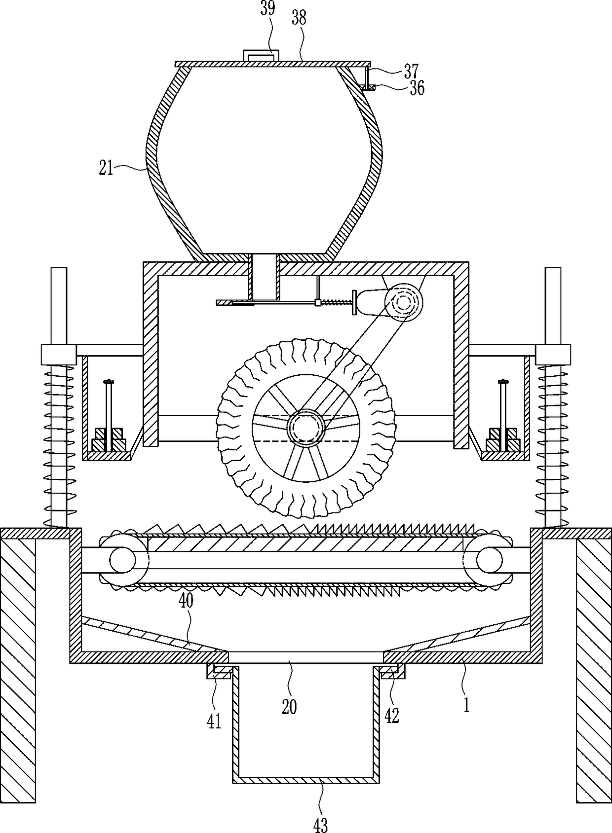
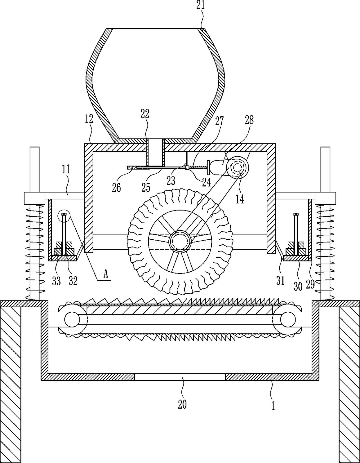
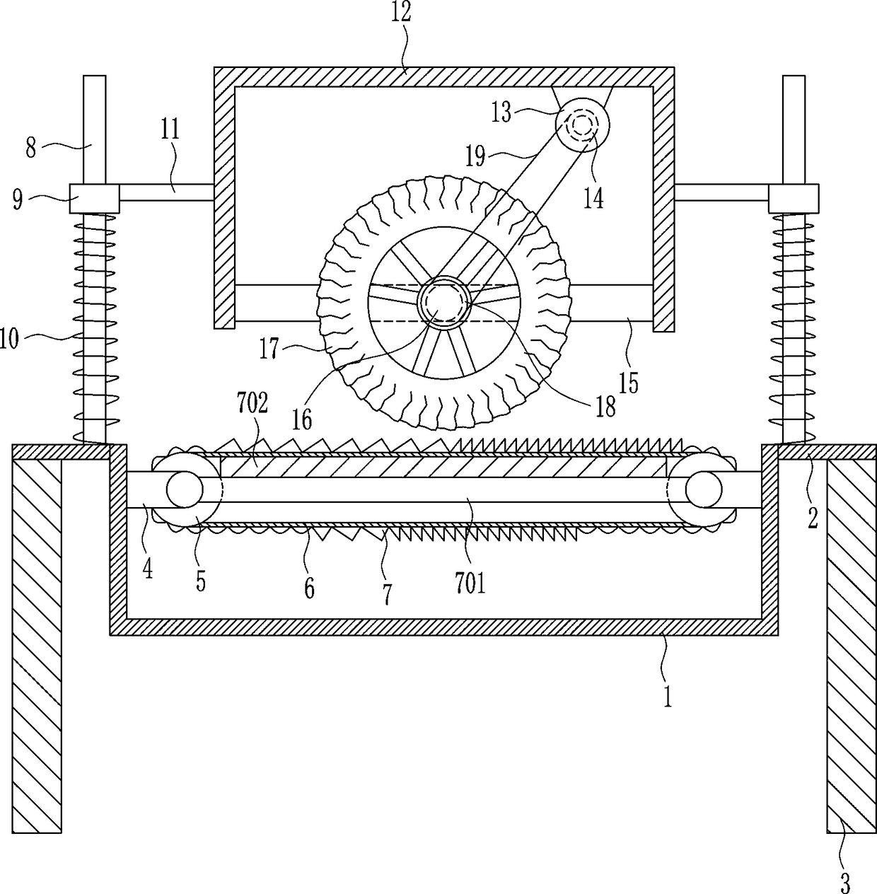
[0022] A device for testing the wear resistance of automobile tires, such as Figure 1-4 As shown, it includes a U-shaped housing 1, a connecting plate 2, a leg 3, a mounting plate 4, a first pulley 5, a first flat belt 6, a rough block 7, a support rod 701, a support plate 702, a slide bar 8, Sliding sleeve 9, first spring 10, cross plate 11, n-shaped frame 12, servo motor 13, second pulley 14, fixed plate 15, first rotating shaft 16, automobile tire body 17, the third pulley 18 and the second flat belt 19. The upper part of the left and right sides of the U-shaped housing 1 is connected with the connecting plate 2, the bottom of the connecting plate 2 is connected with the outrigger 3, and the upper part of the inner wall of the U-shaped housing 1 is connected with the mounting plate 4, and the mounting plate The rear side of 4 is connected with the first pulley 5 in a rotary manner, and the first flat belt 6 is wound between the two first pulleys 5. The first flat belt 6 is...

Embodiment 2

[0024] A device for testing the wear resistance of automobile tires, such as Figure 1-4As shown, it includes a U-shaped housing 1, a connecting plate 2, a leg 3, a mounting plate 4, a first pulley 5, a first flat belt 6, a rough block 7, a support rod 701, a support plate 702, a slide bar 8, Sliding sleeve 9, first spring 10, cross plate 11, n-shaped frame 12, servo motor 13, second pulley 14, fixed plate 15, first rotating shaft 16, automobile tire body 17, the third pulley 18 and the second flat belt 19. The upper part of the left and right sides of the U-shaped housing 1 is connected with the connecting plate 2, the bottom of the connecting plate 2 is connected with the outrigger 3, and the upper part of the inner wall of the U-shaped housing 1 is connected with the mounting plate 4, and the mounting plate The rear side of 4 is connected with the first pulley 5 in a rotary manner, and the first flat belt 6 is wound between the two first pulleys 5. The first flat belt 6 is ...

Embodiment 3

[0027] A device for testing the wear resistance of automobile tires, such as Figure 1-4 As shown, it includes a U-shaped housing 1, a connecting plate 2, a leg 3, a mounting plate 4, a first pulley 5, a first flat belt 6, a rough block 7, a support rod 701, a support plate 702, a slide bar 8, Sliding sleeve 9, first spring 10, cross plate 11, n-shaped frame 12, servo motor 13, second pulley 14, fixed plate 15, first rotating shaft 16, automobile tire body 17, the third pulley 18 and the second flat belt 19. The upper part of the left and right sides of the U-shaped housing 1 is connected with the connecting plate 2, the bottom of the connecting plate 2 is connected with the outrigger 3, and the upper part of the inner wall of the U-shaped housing 1 is connected with the mounting plate 4, and the mounting plate The rear side of 4 is connected with the first pulley 5 in a rotary manner, and the first flat belt 6 is wound between the two first pulleys 5. The first flat belt 6 is...


PUM


Abstract

The invention relates to a testing device for abrasion resistance of a tire, in particular to a testing device for abrasion resistance of an automobile tire. The technical problem of the invention isto provide a testing device for abrasion resistance of an automobile tire which is capable of automatically testing the abrasion resistance of the automobile tire, convenient for observing abrasion degree of the automobile tire, and capable of reducing the labor intensity. The technical implementation scheme of the invention is as follows: the testing device for abrasion resistance of the automobile tire comprises a U-shaped housing, connecting plates, supporting legs, a mounting plate, and a first belt pulley, wherein upper parts of left and right sides of the U-shaped housing are connected with the connecting plates, and the supporting legs are connected to the bottoms of the connecting plates. A first rotating shaft of the testing device provided by the invention rotates to drive an automobile tire body to rotate, the automobile tire body rotates to produce friction with rough blocks with different degrees of roughness on a first flat belt, so as to test the abrasion resistance of the automobile tire body, thereby being able to automatically test the abrasion resistance of the automobile tire, convenient for observing the abrasion degree of the automobile tire, and capable of reducing the labor intensity.

Description

technical field [0001] The invention relates to a tire wear resistance test device, in particular to an automobile tire wear resistance test device. Background technique [0002] In order to increase the sales of automobile tires and enhance the brand awareness of automobile tires, it is necessary to continuously improve the quality of automobile tires. To improve the quality of automobile tires, it is first necessary to master the wear resistance of automobile tires. To master the wear resistance of automobile tires, it is necessary Test the abrasion resistance of automobile tires. At present, the test of automobile tire abrasion resistance is generally to drive the automobile to make the automobile tires roll on the road with different roughness, and then observe the wear degree of the automobile tires, but this method is relatively ineffective. It is convenient to observe the degree of wear of car tires, and it is labor-intensive for people to drive a car on the road for ...

Claims


Application Information

Patent Timeline
Patent Type & Authority Applications(China)
IPC IPC(8): G01N3/56G01M17/02
CPCG01M17/02G01N3/56G01N3/565
Inventor 王鑫阳
Owner CHAOHU WEINENG OPTOELECTRONICS TECH CO LTD
Why Eureka
Try Eureka