Optical fingerprint recognition module

A fingerprint identification module, optical technology, applied in character and pattern recognition, instruments, computer parts, etc., can solve the problems of high cost setting, difficult development, competitive advantage, large space occupation, etc.

Active Publication Date: 2018-12-07
PRIMAX ELECTRONICS LTD
View PDF6 Cites 3 Cited by
  • Summary
  • Abstract
  • Description
  • Claims
  • Application Information

AI Technical Summary

Problems solved by technology

However, if its technology has other deficiencies other than high-cost setup or large space occupation, such as the most

Method used


Image

  • Optical fingerprint recognition module
  • Optical fingerprint recognition module
  • Optical fingerprint recognition module

Examples


Embodiment Construction

[0035] The following is a detailed description of the embodiments, which are only used as examples for illustration and will not limit the scope of protection of the present invention. In addition, the drawings in the embodiments omit elements that are not necessary or can be completed with common technology, so as to clearly show the technical characteristics of the present invention.

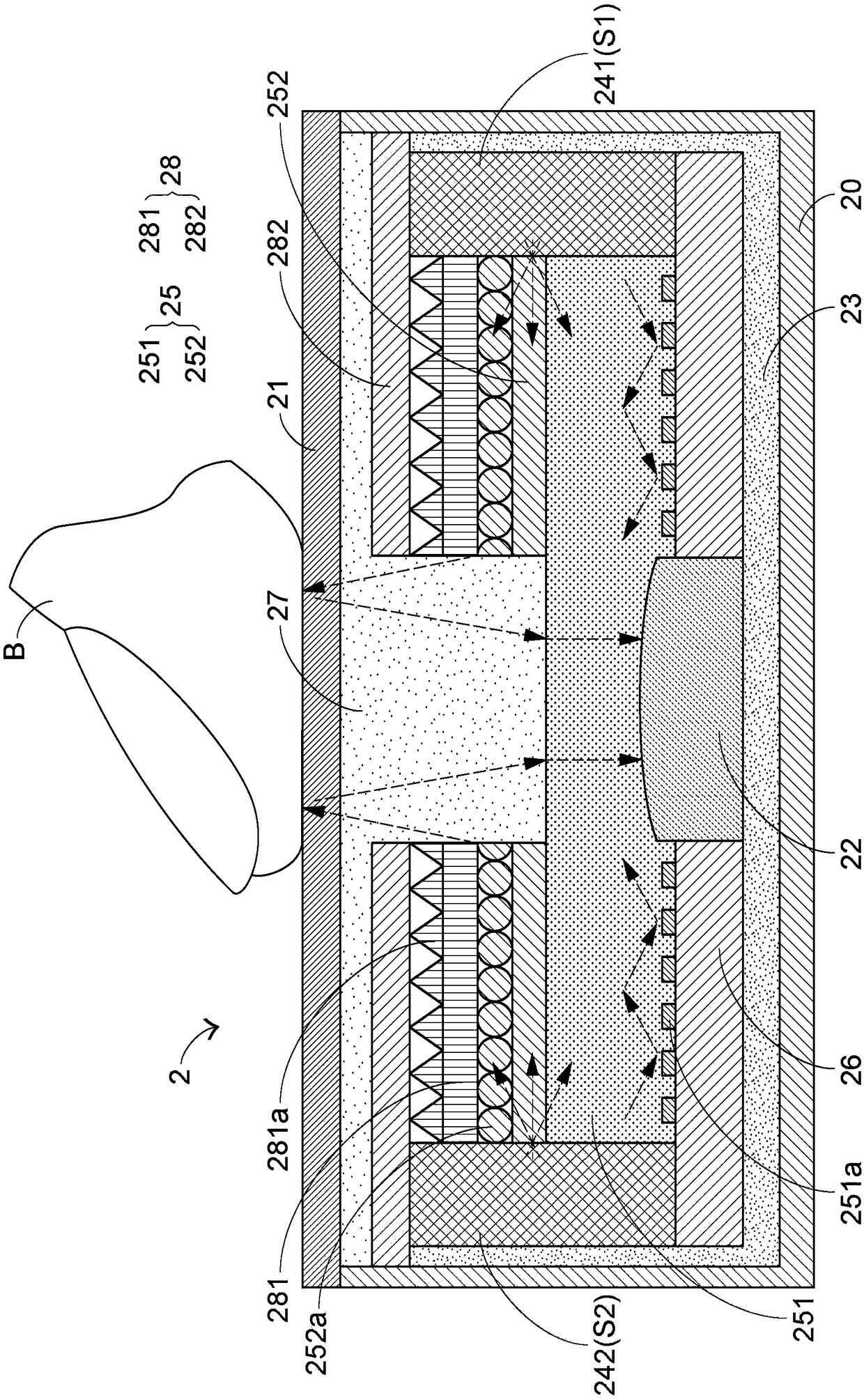
[0036] The implementation description of the present invention is now carried out with a first embodiment. See figure 2 , which is a schematic cross-sectional view of an optical fingerprint recognition module 2 proposed in the first embodiment. Such as figure 2 As shown, the optical fingerprint identification module 2 includes a housing 20, an image acquisition component 22, a light guiding diffusion layer 25, a light concentrating reflection layer 28, a pressing plate 21, two light sources 241, 242, and an optical channel structure 27 and a bottom reflector 26 . In the first embodiment,...


PUM


Abstract

The invention relates to an optical fingerprint recognition module, comprising: a casing, an image acquisition component, a light guiding diffusion layer, a light collecting reflective layer, a pressing plate, at least one light source and a light channel structure. The light channel structure is formed below the pressing plate and above the image acquisition component, passes through the light collecting reflective layer and a portion of the light guiding diffusion layer, and is surrounded by the light collecting reflective layer and a portion of the light guiding diffusion layer. The light emitted by the at least one light source can form conduction and diffusion in the light guiding diffusion layer, and can form condensation and reflection in the light collecting reflective layer, and the light emitted by the at least one light source can be reciprocated between the light guiding diffusion layer and the light collecting reflective layer, then irradiated onto the pressing plate via the light channel structure, and then reflected onto the image acquisition component to be acquired. The optical fingerprint recognition module allows the use of light to be more effectively increased.

Description

technical field [0001] The invention relates to the technical field of fingerprint identification, and in particular to an optical fingerprint identification module. The module utilizes multi-level diffusion and light concentrating design, which enables the light to produce repeated refraction, reflection, scattering and transmission, etc., so that the utilization rate of light can be increased more effectively. Background technique [0002] At present, in order to ensure information security, biometric technology has become a key development project in various industries. Among them, fingerprint recognition is the most common and widely used biometric technology. [0003] A fingerprint is a pattern made up of many curved lines. And when zoomed in, these lines show ups and downs like crests and troughs. Thus, the fingerprint feature is the distribution of these lines, and almost everyone has different fingerprint features, making their uniqueness a basis for identificatio...

Claims


Application Information

Patent Timeline
IPC IPC(8): G06K9/00
CPCG06V40/1324
Inventor 徐茂修丁冠堡
Owner PRIMAX ELECTRONICS LTD
Why Eureka
Try Eureka