
Single bimetal plate package structure and packaging method

A bimetallic plate and packaging structure technology, which is applied in the manufacture of electric solid state devices, semiconductor devices, semiconductor/solid state devices, etc. The effect of improving stability and saving manufacturing costs

Active Publication Date: 2018-12-07
JCET GROUP CO LTD
View PDF5 Cites 0 Cited by
  • Summary
  • Abstract
  • Description
  • Claims
  • Application Information

AI Technical Summary

Problems solved by technology

[0004] However, in the above-mentioned method, in the existing POP manufacturing process, it is necessary to groove the plastic package and form interconnection solder balls by solder printing, the manufacturing process is complicated, and the cost is relatively high.
[0005] PiP package is also a very typical semiconductor stacked package. It stacks multiple semiconductor chips in a single package to achieve the purpose of miniaturization and high density. However, when several semiconductor chips are stacked, the upper chip often requires It is smaller than the lower chip, otherwise the upper chip will be pressed to the bonding wire on the lower chip, which will affect the signal transmission of the lower chip
In order to solve this problem, the industry has proposed a stacked package in which copper pillars are set on the substrate to realize the support and signal transmission of the upper chip. However, this structure has relatively high requirements for the upper chip and can only be flip chip, and its Copper pillars with a certain height must be electroplated on the substrate first during manufacture, the manufacturing procedure is more complicated and the production cost is higher

Method used


Image

  • Single bimetal plate package structure and packaging method
  • Single bimetal plate package structure and packaging method
  • Single bimetal plate package structure and packaging method

Examples


Embodiment Construction

[0053] The present invention will be described in detail below in conjunction with specific embodiments shown in the accompanying drawings. However, these embodiments do not limit the present invention, and any structural, method, or functional changes made by those skilled in the art according to these embodiments are included in the protection scope of the present invention.

[0054]It should be noted that terms such as “upper” and “lower” used herein to express relative positions in space are for the purpose of description to describe the relative position of one unit or feature relative to another unit or feature as shown in the drawings. Relationship. The spatially relative terms may be intended to encompass different orientations of the package in use or operation in addition to the orientation depicted in the figures. For example, if the device in the figures is turned over, elements described as "below" other elements or features would then be oriented "above" the oth...


PUM


Abstract

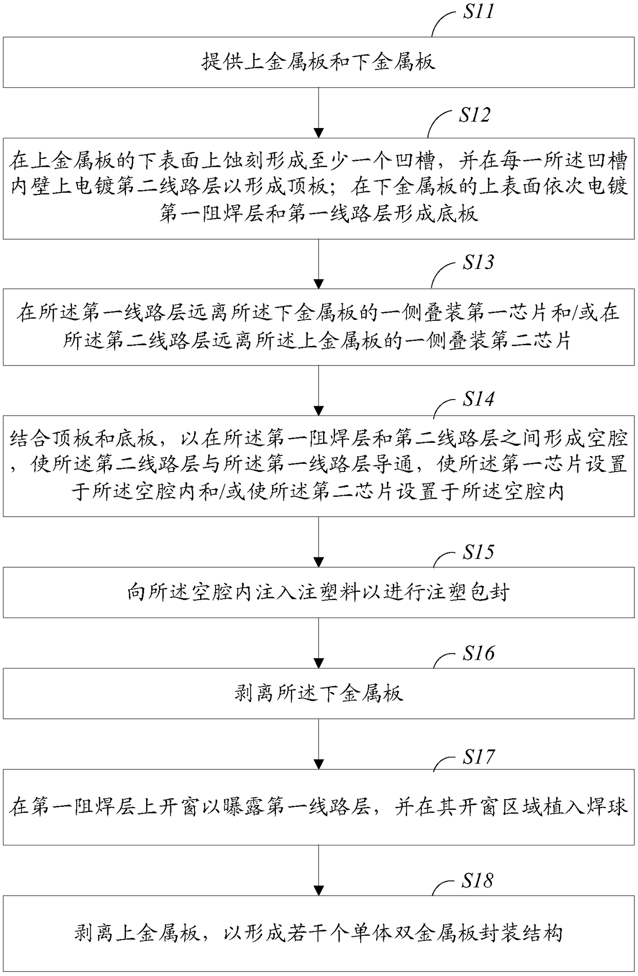
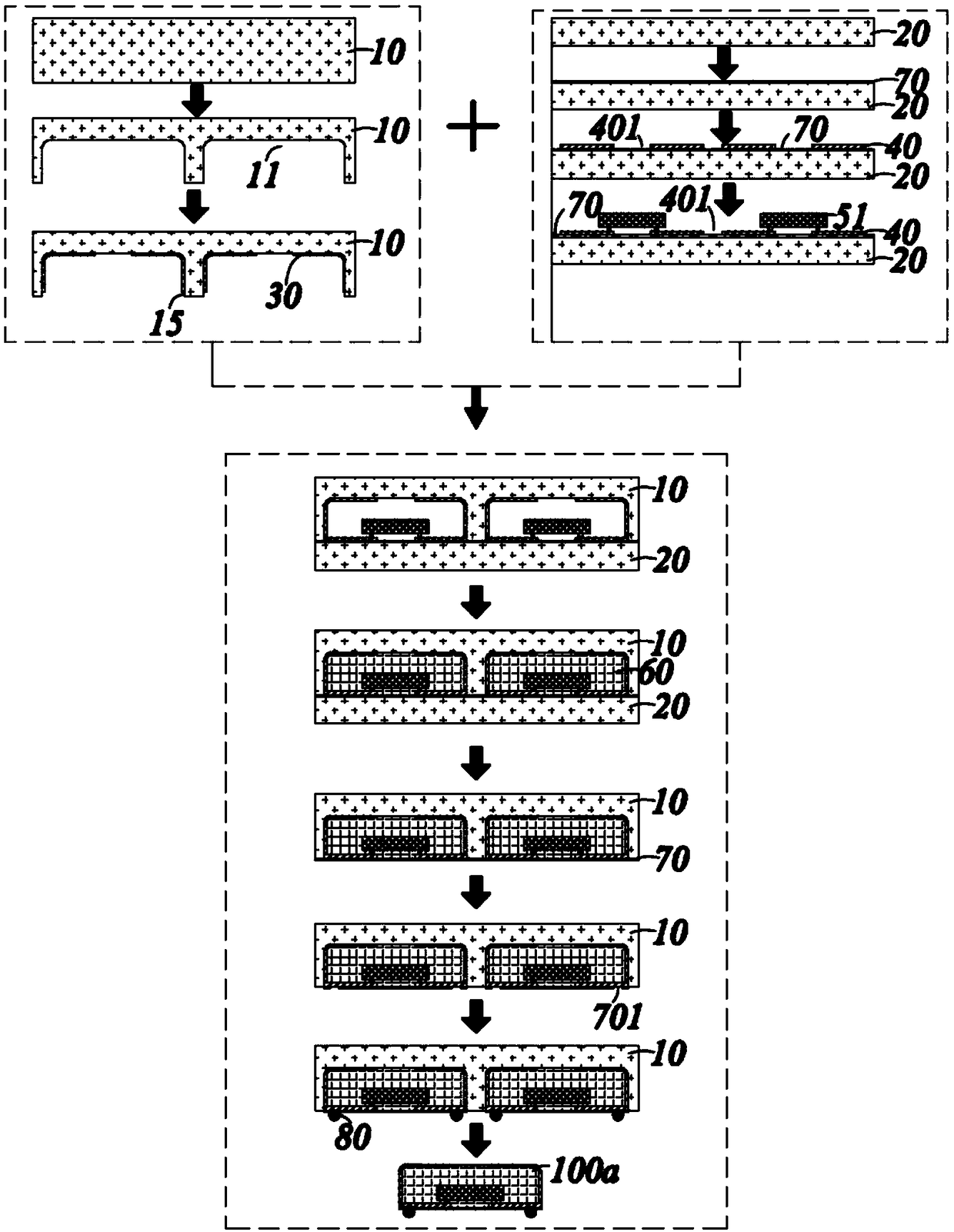
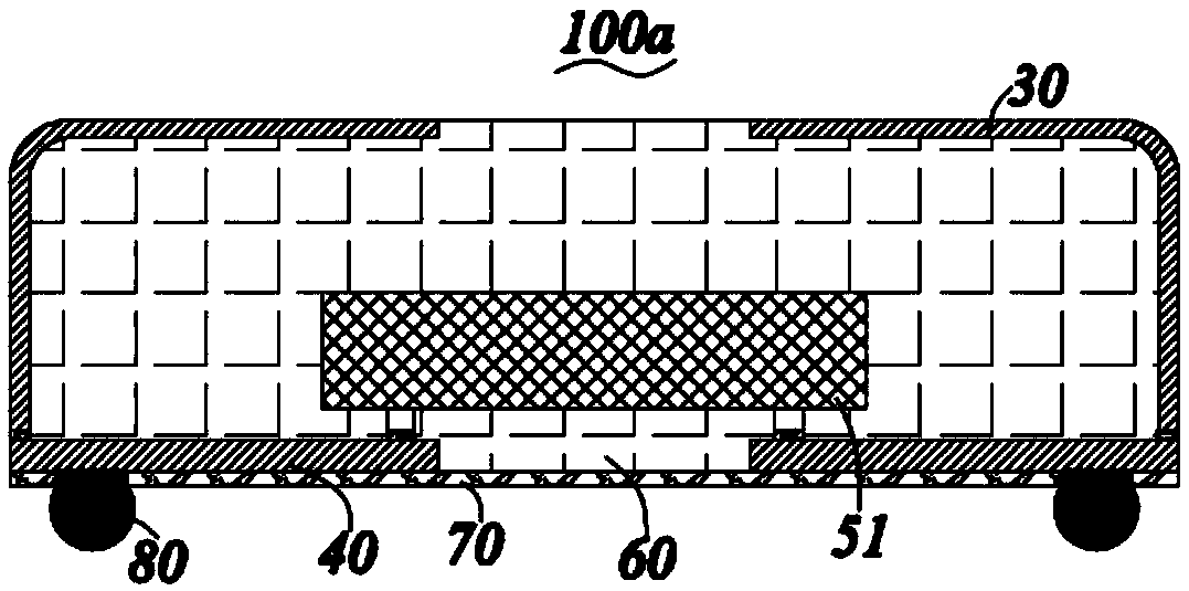
The invention discloses a single bimetal plate package structure and a packaging method. The single bimetal plate package structure comprises: a first circuit layer; a second circuit layer electrically connected on the first circuit layer and forming at least one cavity with the first circuit layer; a first solder mask layer disposed under the first circuit layer, wherein the first solder mask layer is provided with a plurality of windowing regions; injection molding holes disposed at a periphery of the single bimetal package structure and communicated with the interior of the cavity; chips located in the cavity; solder balls implanted in the windowing regions of the first solder mask layer for communicating the first circuit layer, and an injection molding material for filling the cavityand the injection molding holes. The invention realizes the stacked package by connecting the circuit to the surface or the inside of the injection molding material by using the bimetal plate for packaging, the traditional cavity mold is not required for plastic package, the manufacturing cost is saved, the package structure obtained by the method is greatly improved in terms of yield and stability, and the process is simple.

Description

technical field [0001] The invention belongs to the field of semiconductor manufacturing, and in particular relates to a single bimetal plate packaging structure and a packaging method. Background technique [0002] With the trend of multi-function and miniaturization of electronic products, high-density microelectronic assembly technology has gradually become the mainstream in the new generation of electronic products. In order to cooperate with the development of a new generation of electronic products, especially the development of smart phones, handheld computers, ultrabooks and other products, the packaging of integrated circuits is also developing in the direction of miniaturization, high density, high power, and high speed, and stacked packaging is exactly Developed in response to its high-density needs. [0003] POP package is a typical semiconductor stack package. In the field of logic circuits and memory, it has been the first choice in the industry. It is mainly ...

Claims


Application Information

Patent Timeline
Patent Type & Authority Applications(China)
IPC IPC(8): H01L21/56H01L23/31
CPCH01L21/568H01L23/3114H01L2224/16245H01L2224/48091H01L2224/73265H01L2924/181H01L2924/00012H01L2924/00014
Inventor 刘恺梁志忠王亚琴
Owner JCET GROUP CO LTD
Learn More