Solar light splitting tile and greenhouse

A technology of solar energy and solar chimney, which is applied in the field of agricultural engineering, can solve the problems of insufficient utilization of light and heat resources in greenhouses, and achieve the effects of improving optical utilization efficiency, improving production efficiency and economic benefits, and convenient operation

Pending Publication Date: 2018-12-11
INST OF ENVIRONMENT & SUSTAINABLE DEV IN AGRI CHINESE ACADEMY OF AGRI SCI
View PDF0 Cites 1 Cited by
  • Summary
  • Abstract
  • Description
  • Claims
  • Application Information

AI Technical Summary

Problems solved by technology

[0006] The object of the present invention is to provide a solar light splitting tile and a greenhouse. By separating the energy of the visible light required by plants from the unnecessary infrared light, the visible light can enter the interior of the greenhouse, and the energy of the infrared light can be collected to solve the problem of existing greenhouses. Technical Problems of Insufficient Utilization of Photothermal Resources

Method used


Image

  • Solar light splitting tile and greenhouse
  • Solar light splitting tile and greenhouse
  • Solar light splitting tile and greenhouse

Examples


Embodiment 1

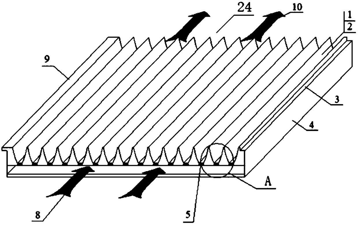
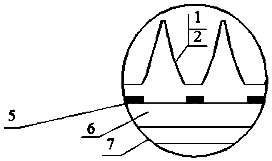
[0034] Such as figure 1 with figure 2 As shown, Embodiment 1 of the present invention provides a solar energy splitting tile 24, which has plant spectrum selection characteristics, and includes a splitting tile body, and the splitting tile body includes a top plate and a bottom plate 7 arranged at intervals up and down, specifically, the The top plate and the bottom plate 7 are arranged in parallel, leaving a gap between the two to form an air channel 6 connected along the length direction of the opening groove 1, the air channel 6 is used for air flow, and the upper surface of the top plate is provided with side-by-side A plurality of opening grooves 1, the inner surface of the opening groove 1 is a compound paraboloid, and the top plate is covered with a light-splitting film 2 that is all bonded to the inner surface of each of the opening grooves 1, and the light-splitting film 2 has a certain effect on the solar spectrum. Selective characteristics, the light splitting fil...

Embodiment 2

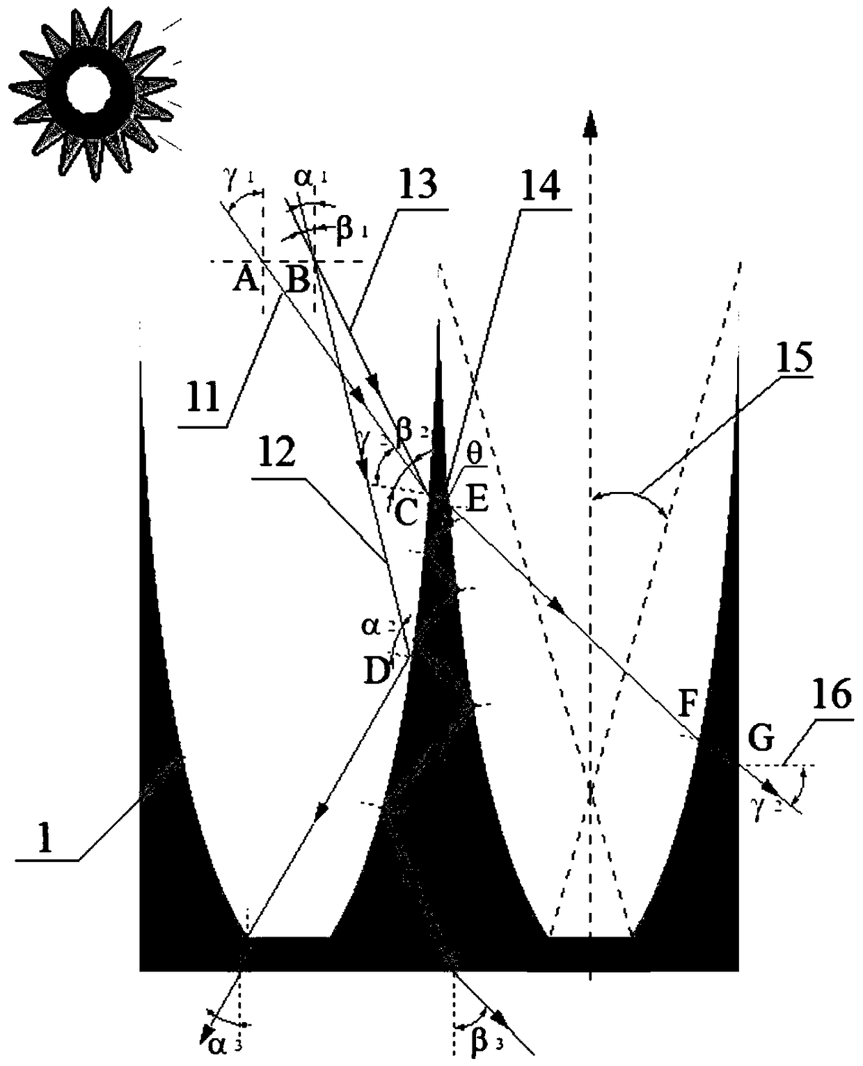
[0042] Embodiment 2 of the present invention provides a kind of greenhouse, such as Figure 4 with Figure 5 As shown, it includes a sloping roof and the above-mentioned solar light splitting tile 24, and the incident light 17 of sunlight is irradiated on the solar light splitting tile 24, and the solar light splitting tile 24 is inclined on the sun-facing surface of the roof. On the roof, the so-called sunny side is the side with the strongest sunlight and is the opposite side of the shady side. The lower port of the air passage 6 is the air inlet, and the upper port of the air passage 6 is the air outlet. The open slot 1 can be used as a rain gutter, and the rainwater flows down the roof along the open slot 1; the heat collecting plate is used to collect the heat of infrared light in the sunlight, and at the same time heat up the air in the air duct. The gas in the inner cavity of the air channel 6 is under the influence of the higher temperature heat collecting plate 5, th...


PUM


Abstract

The invention relates to the field of agricultural engineering and discloses a solar light splitting tile and greenhouse. The solar light splitting tile comprises a solar light splitting tile body including a top board and a bottom board, both of which are spaced vertically. Multiple opening grooves are arranged in the upper surface of the top surface side by side. Inner surfaces of the opening grooves are equipped with composite paraboloids. The top board is equipped with a light splitting film attached to inner surfaces of all the opening grooves in a covering manner. The light splitting film is used for obstructing infrared light of sunlight by visible light of sunlight. An air passage is formed between the top board and the bottom board and communicates along the length directions of the opening grooves. The lower surface of the groove bottom of each opening groove is equipped with a heat collection board used for collecting heat quantity of infrared light. Each heat collection board extends along the length direction of each opening groove. The bottom board is equipped with air holes communicating with the air passage. Utilization of sunlight is achieved in a fractional frequency manner so that energy utilization rate is raised.

Description

technical field [0001] The invention relates to the technical field of agricultural engineering, in particular to a solar light splitting tile and a greenhouse. Background technique [0002] At present, in the integration of solar energy technology and buildings, photothermal technology is the most mature, with the most products and relatively low cost. Among them, solar water heaters are the most widely used. The heat collecting area of ​​Chinese solar water heaters ranks first in the world. However, the existing solar heat collecting devices cannot be well combined with the top of the building, which is inconvenient to install, and becomes an obstacle to the visual appearance and affects the overall image of the building. [0003] In all buildings, the greenhouse exists as a special form. On the one hand, the greenhouse can transmit light to meet the growth needs of different plants, and on the other hand, it can keep the plants inside warm or warm. Generally speaking, ...

Claims


Application Information

Patent Timeline
Patent Type & Authority Applications(China)
IPC IPC(8): A01G9/14A01G9/24F24S20/69
CPCA01G9/14A01G9/243A01G9/246Y02A40/25
Inventor 伍纲张义杨其长方慧
Owner INST OF ENVIRONMENT & SUSTAINABLE DEV IN AGRI CHINESE ACADEMY OF AGRI SCI
Why Eureka
Try Eureka