Supercharge Your Innovation With Domain-Expert AI Agents!

Recovery and utilization method of industrial high temperature and high pressure exhaust gas

A waste gas recovery, high temperature and high pressure technology, applied in separation methods, chemical instruments and methods, dispersed particle filtration, etc., can solve the problems of easy turbulent flow of waste gas, influence on utilization effect, low equipment safety, etc., and achieve high waste gas conversion rate, The effect of avoiding turbulent flow of exhaust gas and improving utilization rate

Active Publication Date: 2018-12-11
长治市杨暴热电粉煤灰综合利用股份有限公司
View PDF7 Cites 0 Cited by
  • Summary
  • Abstract
  • Description
  • Claims
  • Application Information

AI Technical Summary

Problems solved by technology

[0003] There are many equipments for waste heat utilization, but less equipment for waste pressure utilization. Some utilization equipment mainly uses waste pressure to compress gas, but the safety of the equipment is not high, and it cannot meet the needs of assembly line operations; there is no limit for the circulation process of waste gas. Position measures make the exhaust gas easy to turbulent flow and affect the utilization effect

Method used


Image

  • Recovery and utilization method of industrial high temperature and high pressure exhaust gas
  • Recovery and utilization method of industrial high temperature and high pressure exhaust gas
  • Recovery and utilization method of industrial high temperature and high pressure exhaust gas

Examples


Embodiment Construction

[0027] In order to make the technical means, creative features, goals and effects achieved by the present invention easy to understand, the present invention will be further described below in conjunction with specific embodiments.

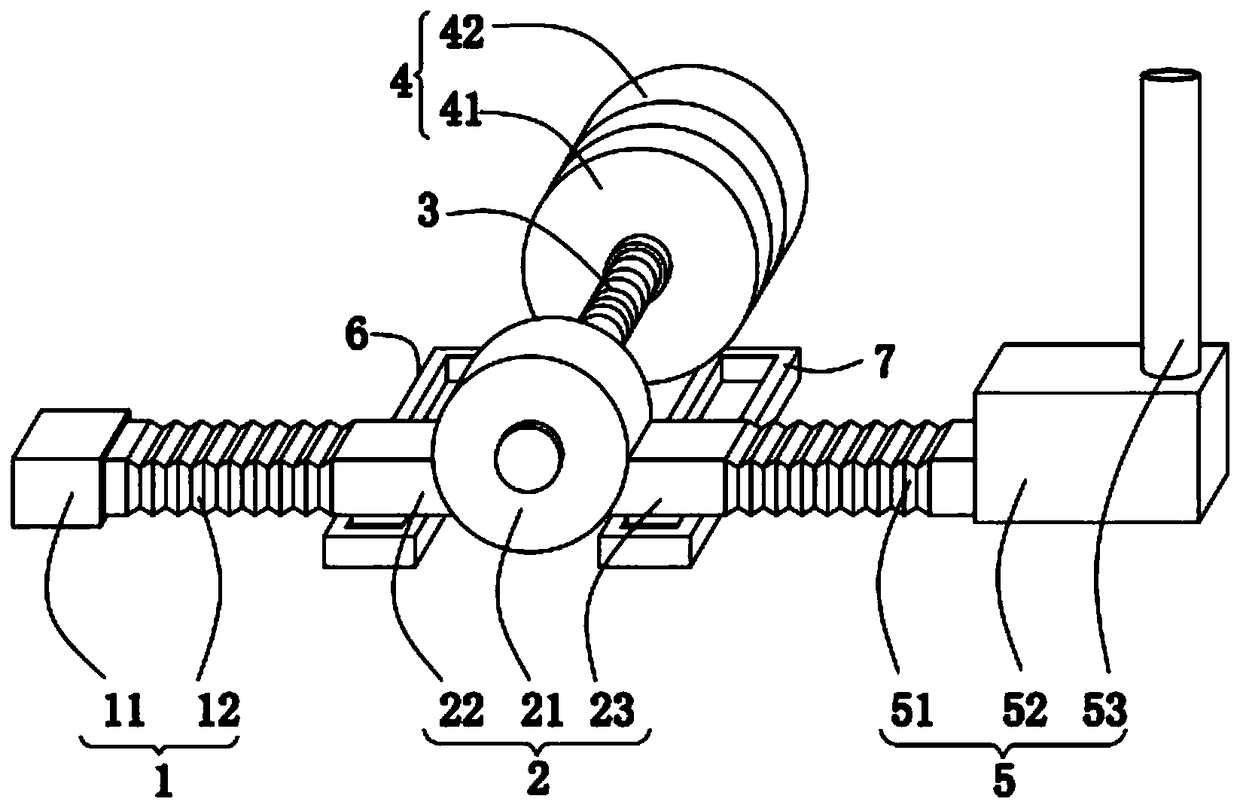
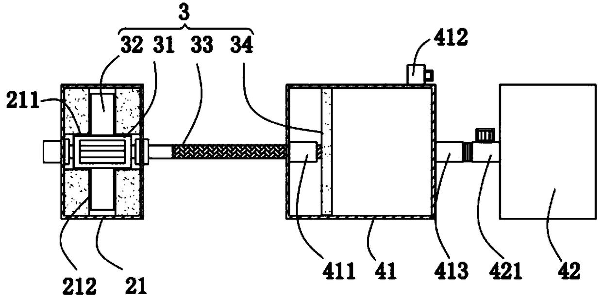
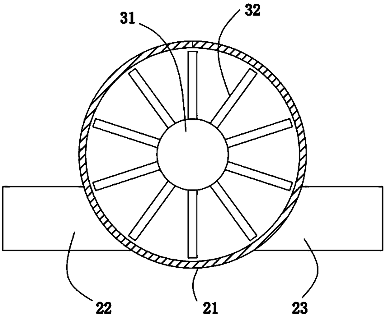
[0028] like Figure 1-Figure 4 As shown, a kind of industrial high temperature and high pressure waste gas recycling method described in the present invention comprises the following steps:

[0029] S1, pass the exhaust gas into the heat exchange device, and the heat exchange device recovers the heat in the exhaust gas;

[0030] S2, passing the waste gas discharged from S2 into a high-pressure waste gas recovery and utilization device, and the high-pressure waste gas recovery and utilization device recycles the high-pressure waste gas under pressure;

[0031] S3, the waste gas discharged in S2 is passed into the dust removal equipment for dust removal, and then discharged into the atmosphere;

[0032] The high-pressure waste gas recycling device...


PUM


Abstract

The invention relates to the technical field of energy source recovery, and specifically a recovery and utilization method of industrial high temperature and high pressure exhaust gas. The high pressure exhaust gas recovery and utilization device used in the method includes an air intake mechanism, an installation mechanism, a transmission mechanism, a pressurization mechanism, an air outlet mechanism, a first sliding seat and second sliding seat. According to the recovery and utilization method, the production of compressed gas can be realized, the pressure energy of the exhaust gas can be changed into the mechanical energy of the transmission mechanism, and the utilization ratio of exhaust gas excess pressure is improved, each tank body is independently arranged, the safety is high, andeach air storage tank is in threaded connection with a pressurization box, an empty gas storage tank can be replaced after pressurization is completed, the requirements of pipeline operation are met;the installation mechanism can move along the sliding seats as a whole, two ends of the installation mechanism are connected with hoses, the installation mechanism can synchronously move by followinga screw on the premise of ensuring the normal circulation of air, so that the needs of the pressurization process are met, the exhaust gas turbulence can be avoided, and the exhaust gas conversion rate is enabled to be higher.

Description

technical field [0001] The invention relates to the technical field of energy recovery, in particular to a method for recycling industrial high-temperature and high-pressure waste gas. Background technique [0002] The waste heat and pressure utilization project is mainly to improve the energy utilization efficiency from the production process. By improving the process structure and adding energy-saving devices, the potential energy and waste heat generated in the production process can be utilized to the greatest extent. [0003] There are many equipments for waste heat utilization, but less equipment for waste pressure utilization. Some utilization equipment mainly uses waste pressure to compress gas, but the safety of the equipment is not high, and it cannot meet the needs of assembly line operations; there is no limit for the circulation process of waste gas. Positional measures make the exhaust gas easy to flow turbulently and affect the utilization effect. Contents o...

Claims


Application Information

Patent Timeline
Patent Type & Authority Applications(China)
IPC IPC(8): B01D46/00B01D46/12B01D53/04F01D15/08
CPCB01D46/0036B01D46/12B01D53/04F01D15/08B01D46/62
Inventor 张家俊
Owner 长治市杨暴热电粉煤灰综合利用股份有限公司
Features
  • R&D
  • Intellectual Property
  • Life Sciences
  • Materials
  • Tech Scout
  • Unparalleled Data Quality
  • Higher Quality Content
  • 60% Fewer Hallucinations
Learn More