
Straw granulation method based on straw granulation equipment

A technology of straw and equipment, applied in the field of straw granulation based on straw granulation equipment, can solve the problems of fire, environmental pollution, serious wear, etc., and achieve the effect of avoiding blockage or damage and having a large blade area.

Inactive Publication Date: 2018-12-11
张家港市欧微自动化研发有限公司
View PDF15 Cites 0 Cited by
  • Summary
  • Abstract
  • Description
  • Claims
  • Application Information

AI Technical Summary

Problems solved by technology

[0002] China's agriculture has a long history. The traditional way of treating straw is to use a small amount of it for raising livestock, and most of it is disposed of by burning. This treatment method not only pollutes the environment, but also poses a fire hazard.
Making straw into granules is a new processing method and process. Due to the structural design defect between the ring die and the pressure roller in the existing straw granulation equipment, the pressure roller rotates at a high degree in the ring die and rubs against the material. A large amount of heat is generated, and the temperature can reach 220 degrees. The high temperature makes the material of the pressing roller brittle, and there is a small amount of hard matter in the straw, so the wear of the pressing roller and the ring die is very serious during the granulation process, and these two materials need to be replaced frequently. Parts, which increase production costs and reduce work efficiency

Method used


Image

  • Straw granulation method based on straw granulation equipment
  • Straw granulation method based on straw granulation equipment
  • Straw granulation method based on straw granulation equipment

Examples


Embodiment Construction

[0083] In order to make the object, technical solution and advantages of the present invention clearer, the embodiments of the present invention will be further described in detail below in conjunction with the embodiments. It should be understood that the specific embodiments described here are only used to explain the embodiments of the present invention, and are not intended to limit the embodiments of the present invention.

[0084]In the description of the present invention, it should be noted that the terms "center", "upper", "lower", "left", "right", "vertical", "horizontal", "inner", "outer" etc. The indicated orientation or positional relationship is based on the orientation or positional relationship shown in the drawings, and is only for the convenience of describing the present invention and simplifying the description, rather than indicating or implying that the referred device or element must have a specific orientation, or in a specific orientation. construction...


PUM


Abstract

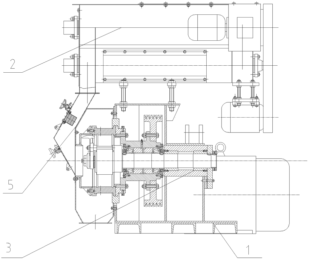
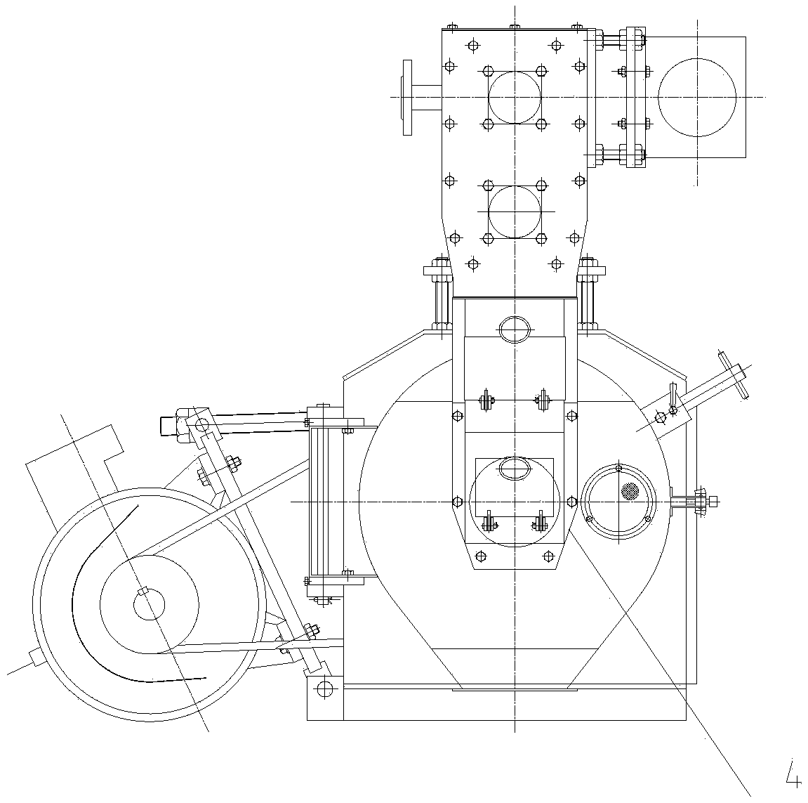
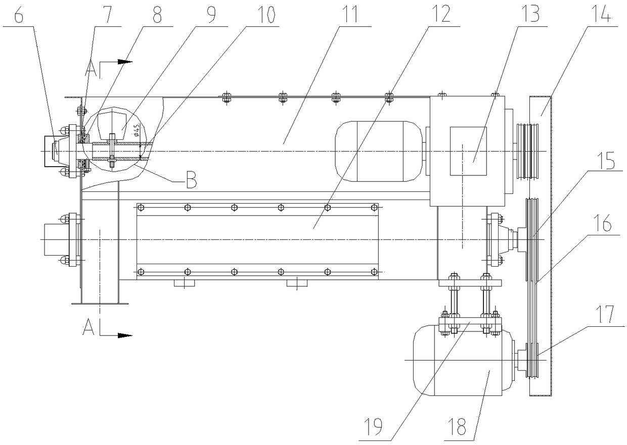
The invention discloses a straw granulation method based on a straw granulation device. The device comprises a rack base, a homogenization device mechanism, a particle molding mechanism, a particle cutting-off mechanism and a discharging mechanism, wherein the particle molding mechanism comprises an annular mold; the annular mold is internally provided with two pressing roller devices; the particle cutting-off mechanism is located at the outer part of part of the particle molding mechanism; the discharging mechanism is located at the left sides of the particle molding mechanism and the particle cutting-off mechanism; pin columns are arranged on an outer surfaces of the pressing roller devices; the contact area of pressing rollers, a material and the annular mold is reduced; the method is adopted so that the abrasion on the pressing rollers and the annular mold can be reduced.

Description

technical field [0001] The invention relates to the field of crop processing, in particular to a straw granulation method based on straw granulation equipment. Background technique [0002] Chinese agriculture has a long history. Traditionally, a small amount of straw is used for raising livestock, and most of them are disposed of by burning. This disposal method not only pollutes the environment, but also poses a fire hazard. Making straw into granules is a new processing method and process. Due to the structural design defect between the ring die and the pressure roller in the existing straw granulation equipment, the pressure roller rotates at a high degree in the ring die and rubs against the material. A large amount of heat is generated, and the temperature can reach 220 degrees. The high temperature makes the material of the pressing roller brittle, and there is a small amount of hard matter in the straw, so the wear of the pressing roller and the ring die is very seri...

Claims


Application Information

Patent Timeline
IPC IPC(8): B01J2/22B01J2/20B01J2/00B01F15/02B01F15/00B01F7/04B01F3/20B01F3/18B01F23/70
CPCB01J2/00B01J2/20B01J2/22B01F23/69B01F23/70B01F23/713B01F23/60B01F27/112B01F27/191B01F27/70B01F35/30B01F35/71
Inventor 黄家旺
Owner 张家港市欧微自动化研发有限公司
Learn More