
Bionic propeller

A propeller, bionic technology, applied in the direction of rotating propellers, rotary propellers, etc., can solve problems such as being in the initial stage, and achieve the effects of increasing stall angle, reducing cavitation noise, and reducing manufacturing costs.

Inactive Publication Date: 2015-05-20
HARBIN ENG UNIV
View PDF7 Cites 9 Cited by
  • Summary
  • Abstract
  • Description
  • Claims
  • Application Information

AI Technical Summary

Problems solved by technology

Foreign scholars put forward the concept of zigzag blade tip based on the low-noise principle of nocturnal owl wings. Some scholars have applied it to the research of eliminating the sound of propellers, but the research on noise reduction is still in its infancy.

Method used


Image

  • Bionic propeller
  • Bionic propeller
  • Bionic propeller

Examples


Embodiment Construction

[0018] The present invention is described in more detail below in conjunction with accompanying drawing example:

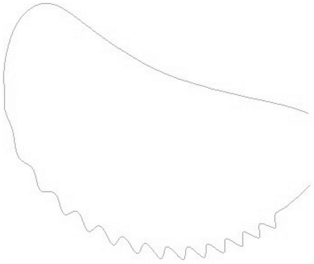
[0019] to combine Figure 1~4 , The leading edge of the blade of the present invention has concavo-convex nodules, and the tip of the blade presents a zigzag shape. It helps to improve the thrust of the propeller, greatly reduces the cavitation of the propeller and helps to improve the noise reduction performance of the propeller, and proposes a new design idea for the propeller of the ship. The mechanism of this technology to increase the hydrodynamic performance of the propeller is that the protrusions on the leading edge generate counter-rotating vortices, which inject power into the liquid flow, making the liquid flow close to the surface, and at the same time, the concave-convex nodes on the leading edge of the wing change the boundary of the wing The thickness of the blade tip interferes with the vortex state in the boundary layer, forming a flow direction ...


PUM


Abstract

The invention aims to provide a bionic propeller. The bionic propeller comprises a blade. A guiding edge portion of the blade is of a concave-convex front edge structure, and a blade tip of the blade is of a sawtoothed structure. The concave-convex front edge structure comprises fourteen protruding nodes, the sizes of the protruding nodes sequentially decrease from the middle of the guiding edge portion to two sides, a smooth transition effect is achieved from the protruding nodes to the blade tip and the blade, and tangent planes at a convex position and a concaved position of each protruding node are both shaped like wing tangent planes. The sawtoothed structure comprises four sawteeth, the sawteeth are distributed in a region of 17 degrees to 25 degrees from the edge to the center line of the blade, inward sawtooth concaves and outward sawtooth cusps are formed in the blade tip of the blade, and the projection of each sawtooth is an isosceles triangle. The bionic propeller enables a boundary separation region on the surface of the blade to be obviously reduced relative to a standard blade, so a stalling angle is increased; the bionic propeller can make full use of the power of a main engine under various working conditions, reduce waste of the power of main engines of a conventional propeller and a ducted propeller, reduce generated cavitation noise, and improve the utilization efficiency of ship energy.

Description

Technical field [0001] The present invention relates to a ship propeller, specifically a propeller. Background technique [0002] As the most common propeller for ships, propellers are used on most ships and their range is very wide. With the development of science and technology, people have higher requirements for the hydrodynamic performance provided by propellers. In recent years, issues such as increasing propeller thrust and efficiency and reducing cavitation have become hot topics in research on propeller hydrodynamic performance. [0003] a. Concave-convex front edge structure [0004] With the development of science and technology, people are no longer satisfied with the hydrodynamic performance provided by traditional wings. In order to increase the lift of the fins, people use the method of imitating the protrusions on the leading edge of the pectoral fins of humpback whales to achieve the purpose of increasing the lift of the fins. A new design idea is propose...

Claims


Application Information

Patent Timeline
Patent Type & Authority Applications(China)
IPC IPC(8): B63H1/26
Inventor 郭春雨姜慧赵大刚
Owner HARBIN ENG UNIV
Learn More