
Water particle generating device

A generation device and particle technology, which is applied in the direction of spraying device, electrostatic spraying device, corona discharge device, etc., can solve the problems of high defective rate and processing cost, extremely high requirements for the shape of the emitter electrode, and obstruction of water particle movement, etc. Reliable electrical connection, excellent atomization effect, and stable condensed water volume

Active Publication Date: 2018-12-11
BEIJING XIAOMI MOBILE SOFTWARE CO LTD +1
View PDF9 Cites 4 Cited by
  • Summary
  • Abstract
  • Description
  • Claims
  • Application Information

AI Technical Summary

Problems solved by technology

[0002] The existing high-voltage corona atomized water particle generating device in the industry, the cooling device cools the emitter electrode, so that the water in the surrounding air condenses on the emitter electrode. When the high-voltage source applies high voltage to the emitter electrode, the condensed The water on the emitter electrode is atomized by the high-voltage corona, and the emitter electrode undertakes the two functions of discharge and condensation. The emitter electrode discharges while collecting condensed water. The requirements for the shape of the emitter electrode are extremely high, and the formed defective products The efficiency and processing cost are high, and the opposite electrode opposite to the emitter electrode is located on the top of the emitter electrode, which has the disadvantage of blocking and hindering the movement of atomized water particles

Method used


Image

  • Water particle generating device
  • Water particle generating device
  • Water particle generating device

Examples


Embodiment 1

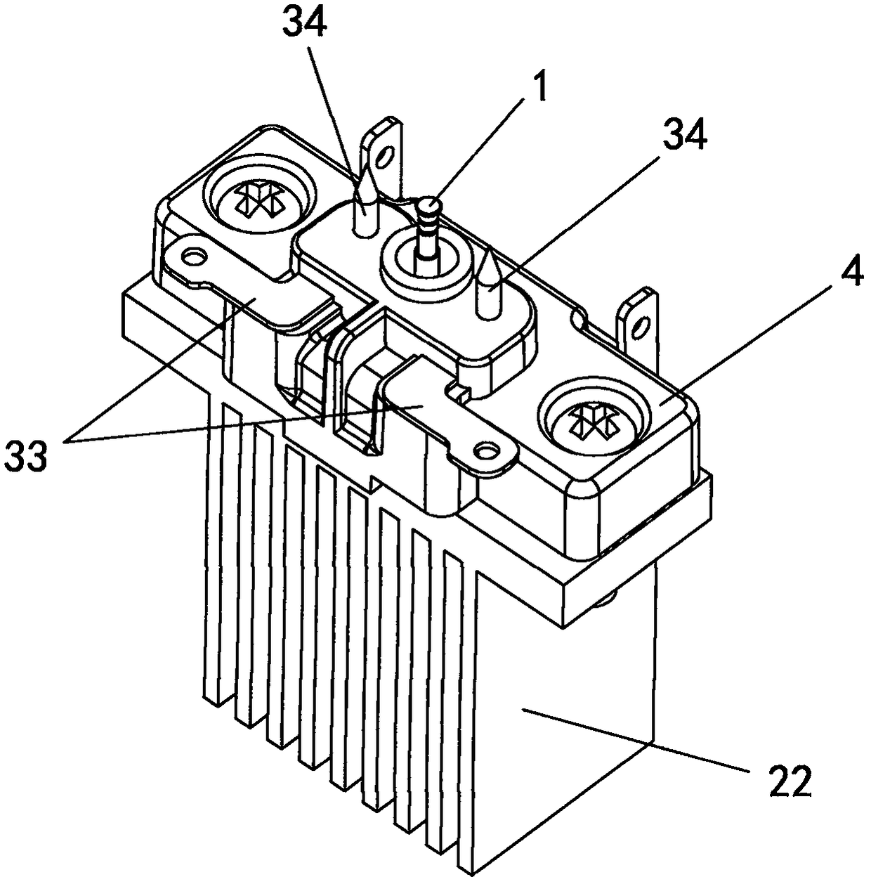
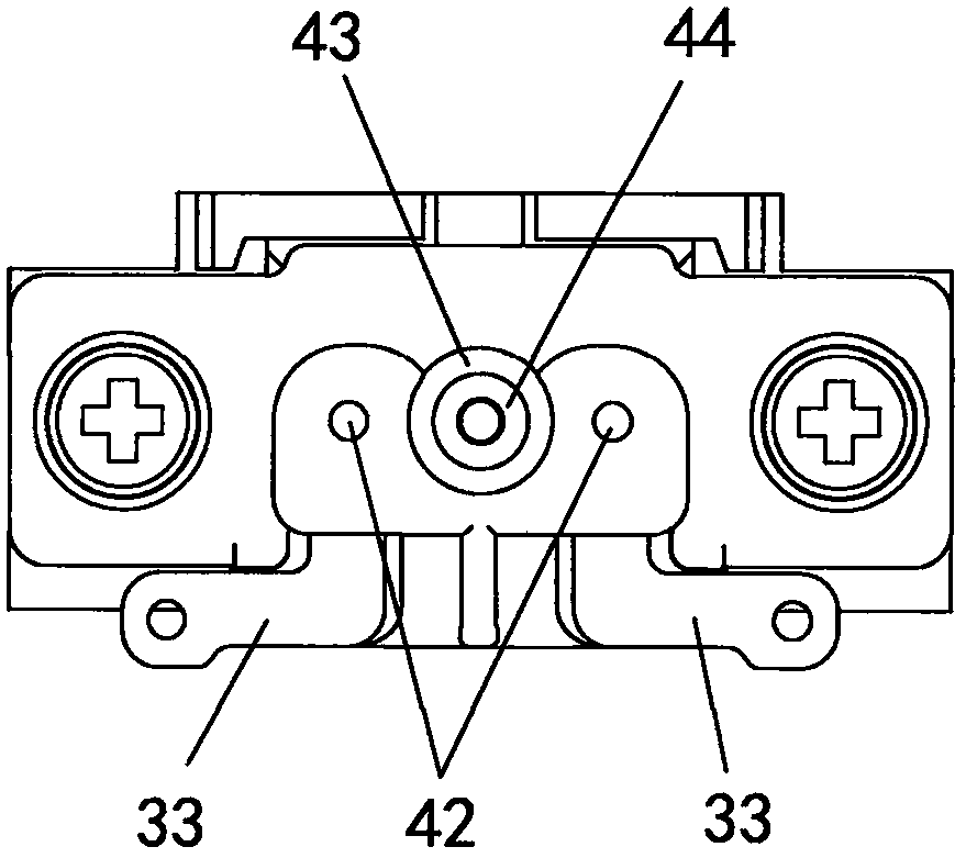
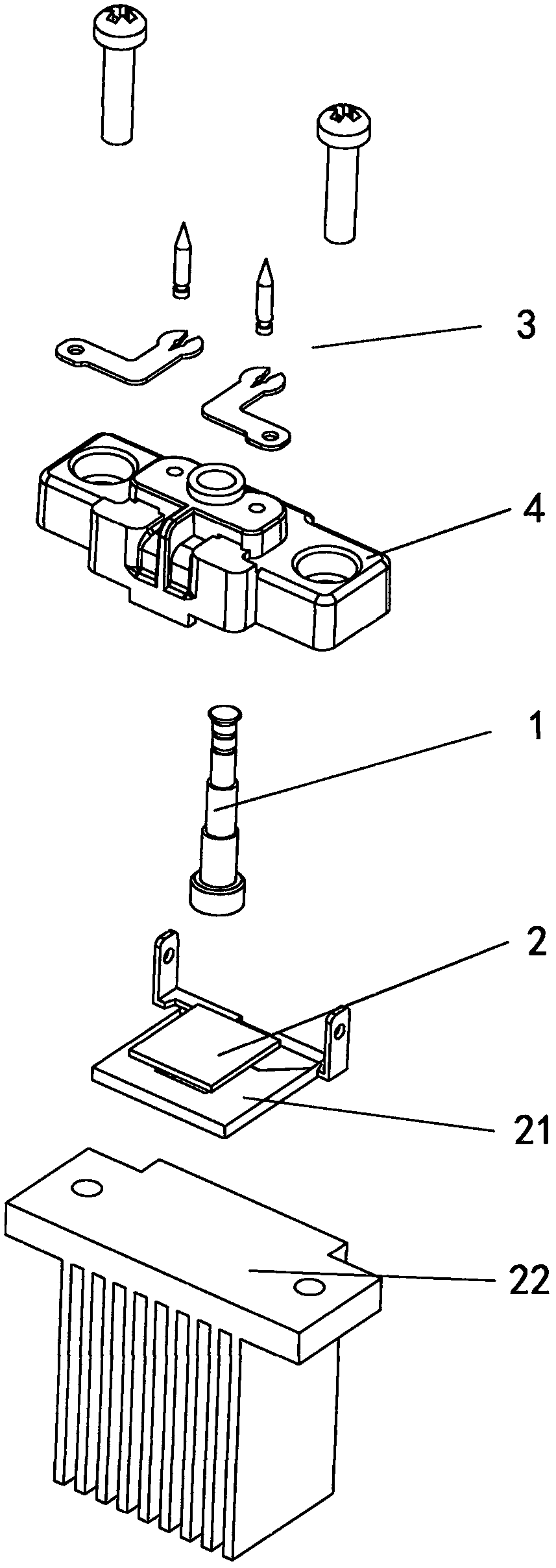
[0037] This embodiment provides a water particle generating device, such as Figure 1 to Figure 7 As shown, a water particle generating device includes: a condensation rod 1, which condenses water in the air around the condensation rod 1 on the condensation rod 1; a refrigerator 2, which contacts the condensation rod 1, and The rod 1 is cooled down; the discharge electrode group 3, the discharge electrode group 3 includes electrode one 31 and electrode two 32 that cooperate with each other, and the electrode one 31 and electrode two 32 are arranged laterally, and the electrode one 31 and electrode two 32 are arranged horizontally. Two 32 are respectively located at both sides of the condensation rod 1; a high-voltage power supply applies a high voltage to the discharge electrode group 3, so that a high-voltage corona is generated between the electrode one 31 and the electrode two 32; wherein, the discharge electrode The electrode group 3 applies a high-voltage corona to the co...

Embodiment 2

[0046] The difference between this embodiment and Embodiment 1 is that, if Figure 8 and Figure 9 As shown, the discharge tip 34 is a discharge needle with a tapered tip, the connecting lock piece 33 is installed on the side of the insulating bracket away from the refrigerator 2, the end of the connecting lock piece 33 wraps the discharge needle, and makes The conical tip of the discharge needle acts on the condensation rod 1. The connecting lock piece 33 of the present invention wraps the discharge needle, which can maximize the contact area between the two, ensure the effect of electrical connection, and avoid sparks at the connection between the two.

[0047] In this embodiment, the condensation surface 11 does not need to be provided with a water collecting tank, and the condensation surface 11 of the condensation rod is also provided with a slow flow step 13 that gradually increases from the top to the bottom of the circumference, which can also realize the guarantee. ...

Embodiment 3

[0049] The difference between this embodiment and Embodiment 1 is that, if Figure 10 In the water particle generating device shown, the discharge tip 34 is a discharge sheet with sharp corners, and the discharge sheet is integrally formed with the connecting lock piece 33 , and the sharp corner of the discharge sheet acts on the condensation rod 1 . The discharge tip 34 is designed in a sheet shape, and is integrally formed with the connecting lock piece 33, which reduces the difficulty of forming the discharge electrode group, and the relative area between the two discharge tips is larger, ensuring that the cooling rod 1 is in a place where the discharge electrode group withstands high voltage. In the generated high-voltage corona, the position of the high-voltage corona and the condensed water is not easily dislocated, and the atomization effect of the condensed water condensed on the condensing rod 1 is better. In this embodiment, the discharge gap L between the discharge ...


PUM


Abstract

The invention relates to a water particle generating device. The water particle generating device comprises a condensation rod, a refrigerator, a discharging electrode group and a high-voltage power supply; water in air around the condensation rod is condensed on the condensation rod; the refrigerator makes contact with the condensation rod and is used for cooling the condensation rod; the discharging electrode group comprises a first electrode and a second electrode which cooperate with each other, and the first electrode and the second electrode are transversely arranged and located on the two sides of the condensation rod correspondingly; and the high-voltage power supply is used for exerting high voltage to the discharging electrode group to enable high-voltage corona to be generated between the first electrode and the second electrode, and the discharging electrode group is used for exerting the high-voltage corona to the condensation rod to enable condensate water attached to thecondensation rod to be excited by the high-voltage corona to generate atomized water particles. According to the water particle generating device, the atomization effect is good, discharging parts are installed steadily, and electrical connection is reliable.

Description

technical field [0001] The invention relates to an atomizing device, in particular to a water particle generating device. Background technique [0002] The existing high-voltage corona atomized water particle generating device in the industry, the cooling device cools the emitter electrode, so that the water in the surrounding air condenses on the emitter electrode. When the high-voltage source applies high voltage to the emitter electrode, the condensed The water on the emitter electrode is atomized by the high-voltage corona, and the emitter electrode undertakes the two functions of discharge and condensation. The emitter electrode discharges while collecting condensed water. The requirements for the shape of the emitter electrode are extremely high, and the formed defective products The efficiency and processing cost are high, and the opposite electrode opposite to the emitter electrode is located on the top of the emitter electrode, which has the disadvantage of blocking...

Claims


Application Information

Patent Timeline
IPC IPC(8): B05B5/025B05B5/053
CPCB05B5/025B05B5/0533B05B5/057B05B5/0536B05B5/0535B05B5/0255B05B5/087B05B5/053H01T19/00
Inventor 肖钊贤
Owner BEIJING XIAOMI MOBILE SOFTWARE CO LTD
Learn More