Supercharge Your Innovation With Domain-Expert AI Agents!

Tool and machining method of special static blade installing hole socket of central machine shell

A central casing and processing method technology, applied in the direction of the boring head, etc., can solve the problems of structural limitations, the inability to design a reverse scribing tool that meets the requirements, and the difficulty in ensuring the accuracy and efficiency of the processing of the special stationary vane installation holes of the central casing. , to achieve remarkable results and improve processing speed

Inactive Publication Date: 2018-12-11
SHENYANG TURBO MASCH CORP
View PDF8 Cites 0 Cited by
  • Summary
  • Abstract
  • Description
  • Claims
  • Application Information

AI Technical Summary

Problems solved by technology

[0002] The central casing of the axial flow compressor has circumferential holes arranged in the axial direction on the circumference, which are used to install the stator vane. The circular inner hole is used to process the stator vane installation hole, but the stator vane installation hole of the central casing of the SACC scale prototype is larger than the installation base hole, so limited by this structure, it is impossible to design a reverse scratch dimple that meets the requirements knives
[0003] In summary, the traditional processing method is difficult to guarantee the accuracy and efficiency of the processing of the special stationary vane installation holes of the central casing

Method used


Image

  • Tool and machining method of special static blade installing hole socket of central machine shell
  • Tool and machining method of special static blade installing hole socket of central machine shell
  • Tool and machining method of special static blade installing hole socket of central machine shell

Examples


Embodiment Construction

[0036] The present invention is described in detail below in conjunction with accompanying drawing:

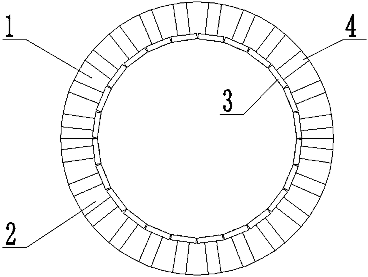
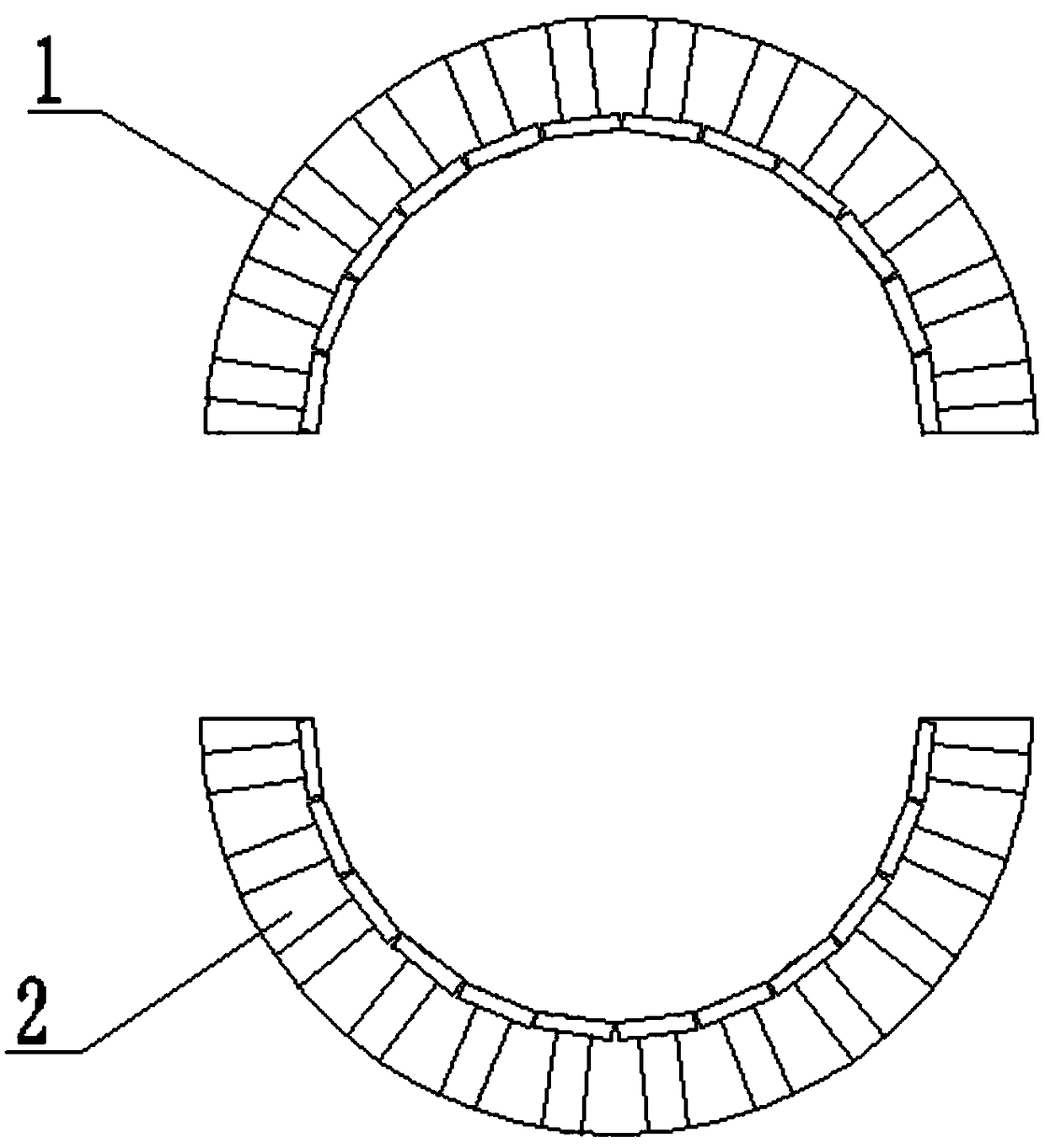
[0037] refer to Figure 1 to Figure 6 , the central casing is a two-half combined structure, that is, it is composed of the bottom plane of the upper central casing 1 and the top plane of the lower central casing 2. A series of holes 3 are arranged on the central casing in a circular shape. The bottom of the socket 3 is provided with a base hole 4, and the axis of rotation of the socket 3 and the axis of rotation of the base hole 4 coincide in space.

[0038] For the hole 3 far away from the split surface of the central casing, the processing steps are as follows:

[0039] A. Refer to figure 1 , figure 2 , using the central casing as a two-half structure, the central casing is disassembled along the split plane;

[0040] B. On the CNC boring machine, use the facet in the casing to find the alignment;

[0041] C. Use the spindle of the boring machine to process the holes ...


PUM


Abstract

The invention discloses a machining tool and a machining method of a special static blade installing hole socket of a central machine shell. The machining method comprises the following steps that machining is carried out on the hole sockets which is far away from a split face in the central machine shell; and the machining is carried out on the hole sockets adjacent to the split face in the central machine shell; the machining of the hole sockets adjacent to the split face in the central machine shell comprises the following steps that a positive scribing socket cutter is installed on a threaded hole part, on a transition shaft, of the end part of a lengthened boring rod; the lengthened boring rod is positioned with a workpiece base hole through a positioning shaft; and the hole socket ismachined in a manner that the extending length of the positive scribing socket cutter is lengthened in the radial direction gradually along the hole socket to be machined; and the invention further discloses a machining tool. The method aims at the hole socket which is far away from the split face in the central machine shell, the machining is carried out by utilizing a boring machine main shaft,the hole socket which is close to the split face in the central machine shell and interfered with the boring machine main shaft is aimed, a combined body of the lengthened boring rod and the positivescribing socket cutter is designed to carry out the machining, so that the high-precision and high-efficiency machining of the special static blade installing hole socket is realized.

Description

technical field [0001] The invention belongs to the field of mechanical processing, and in particular relates to a processing method and a cutting tool for a special static vane installation hole socket of a central casing. Background technique [0002] The central casing of the axial flow compressor has circumferential holes arranged in the axial direction on the circumference, which are used to install the stator vane. The circular inner hole is used to process the stator vane installation hole, but the stator vane installation hole of the central casing of the SACC scale prototype is larger than the installation base hole, so limited by this structure, it is impossible to design a reverse scratch dimple that meets the requirements knives. [0003] To sum up, the traditional processing method is difficult to guarantee the accuracy and efficiency of the processing of the special stationary vane installation holes of the central casing. Contents of the invention [0004]...

Claims


Application Information

Patent Timeline
IPC IPC(8): B23B35/00B23B29/03
CPCB23B29/03B23B35/00
Inventor 李琳舒鑫王强郭峰马秀英金星张威白俊峰范海宇付帅
Owner SHENYANG TURBO MASCH CORP
Features
  • R&D
  • Intellectual Property
  • Life Sciences
  • Materials
  • Tech Scout
  • Unparalleled Data Quality
  • Higher Quality Content
  • 60% Fewer Hallucinations
Learn More