
Ejecting type nut screwing machine and screwing method thereof

A technology for screwing machines and nuts, used in electromechanical devices, manufacturing motor generators, metal processing, etc., can solve problems such as inability to rotate, large bolts, pressure loss, etc., achieve a compact and reasonable overall structure, improve equipment integration, and ensure The effect of part quality

Active Publication Date: 2018-12-11
KUNSHAN JIEYUN INTELLIGENT EQUIP CO LTD
View PDF14 Cites 4 Cited by
  • Summary
  • Abstract
  • Description
  • Claims
  • Application Information

AI Technical Summary

Problems solved by technology

[0003] When the usual jack-up nut screwing machine is in operation, the semi-finished motor with the pulley installed is usually placed on the pallet. After the pallet is transported to the screwing position along the conveyor line (roller line), the nut is driven down by a special electric batch. Screwed on the rotor shaft of the semi-finished motor, during the screwing process, the downward pressure will cause a certain load on the conveying line and the tray, which will easily cause problems such as deformation and pressure loss, which will affect their use
[0004] At the same time, when screwing, since the rotor shaft is in a rotatable state, it is necessary to fix the rotor shaft with special equipment so that it cannot rotate, so as to achieve effective screwing, which adds an additional fixing structure, causing the equipment to Complex structure
[0005] In addition, because the volume of bolts is larger than that of screws, it is not easy to absorb them through the head. Therefore, before screwing, it is necessary to combine the bolts with automatic equipment such as clamping jaws to place the bolts on the rotor shaft, which further increases the complexity of the equipment. sex

Method used

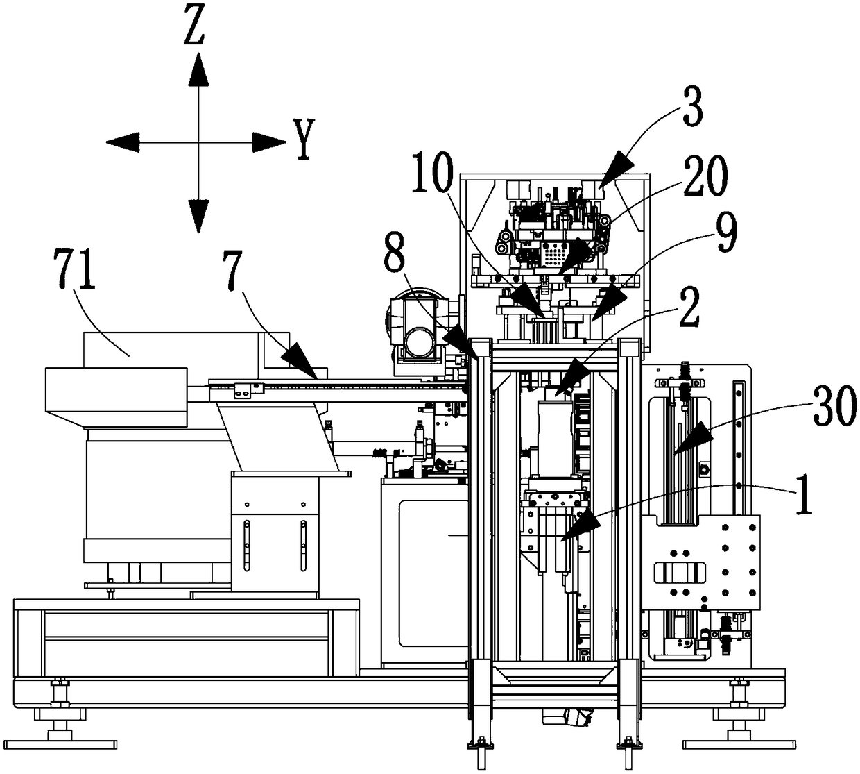
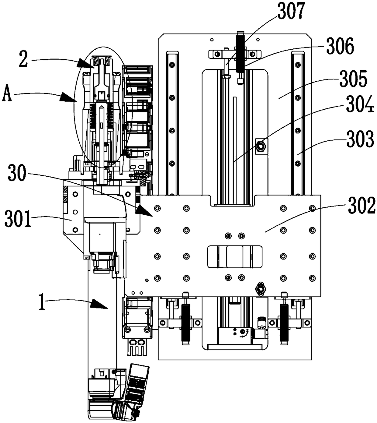
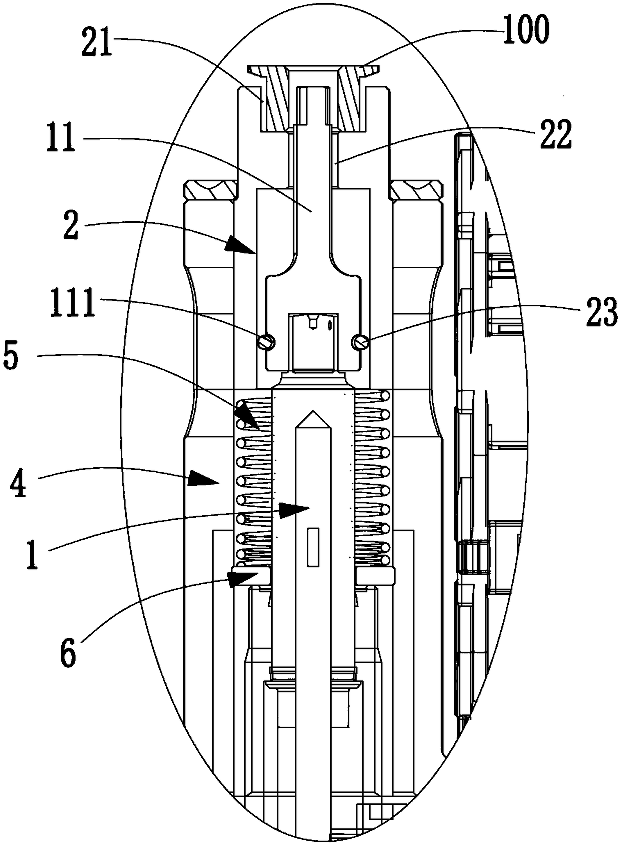

Image

  • Ejecting type nut screwing machine and screwing method thereof
  • Ejecting type nut screwing machine and screwing method thereof
  • Ejecting type nut screwing machine and screwing method thereof

Examples


Embodiment Construction

[0040] Objects, advantages and features of the present invention will be illustrated and explained by the following non-limiting description of preferred embodiments. These embodiments are only typical examples of applying the technical solutions of the present invention, and all technical solutions formed by adopting equivalent replacements or equivalent transformations fall within the protection scope of the present invention.

[0041] In the description of the scheme, it should be noted that the terms "center", "upper", "lower", "left", "right", "front", "rear", "vertical", "horizontal", " The orientation or positional relationship indicated by "inner", "outer", etc. is based on the orientation or positional relationship shown in the drawings, and is only for the convenience of description and simplification of description, rather than indicating or implying that the device or element referred to must have a specific orientation , constructed and operated in a particular or...


PUM


Abstract

The invention discloses an ejecting type nut screwing machine and a screwing method thereof. The screwing machine comprises an electric screwdriver, a floating sleeve and a fixing device, wherein theelectric screwdriver at least can perform longitudinal reciprocating movement, and an electric screwdriver head of the electric screwdriver faces upwards; in a normal state, the floating sleeve sleeves the electric screwdriver head of the electric screwdriver, and can float up and down relative to the electric screwdriver head, and a hole used for limiting a nut is formed in the top part of the floating sleeve, and the electric screwdriver head extends into the hole in the normal state; and the fixing device is used for fixing a second component and enabling a self-rotating to-be-screwed parton the second component to be coaxial with the floating sleeve. According to the machine and the method, the design is ingenious, the structure is simple, the ejecting mode is adopted for the screwing, so that the pressure generated by conventional operation on a conveying line and a material tray is avoided, and protection of the conveying line and the material tray can be facilitated; when in assembly, an ingenious floating structure is combined with the electric screwdriver, a mode of driving a rotor shaft to rotate and ejecting the nut is adopted, so that the assembling of a belt wheel andthe rotor shaft is effectively achieved, the structure of fixing the rotor shaft is omitted, and the simplifying of the overall structure of the equipment is facilitated.

Description

technical field [0001] The invention relates to nut screwing equipment, in particular to a jack-up nut screwing machine and a screwing method thereof. Background technique [0002] At present, in the field of automatic assembly production lines of automobile engines and new energy motors, there are often screwing operations that need to connect nuts to parts with external threads. For example, after assembling the pulley on the rotor shaft, it needs to be fixed by nuts. [0003] When the usual jack-up nut screwing machine is in operation, the semi-finished motor with the pulley installed is usually placed on the pallet. After the pallet is transported to the screwing position along the conveyor line (roller line), the nut is driven down by a special electric batch. Screwed on the rotor shaft of the semi-finished motor, during the screwing process, the down force will cause a certain load on the conveyor line and the tray, which will easily cause problems such as deformation ...

Claims


Application Information

Patent Timeline
Patent Type & Authority Applications(China)
IPC IPC(8): B23P19/06H02K15/00
CPCH02K15/00B23P19/06
Inventor 秦学刚刘超波彭波
Owner KUNSHAN JIEYUN INTELLIGENT EQUIP CO LTD
Learn More