Automatic polishing cutter assembly device

A technology of automatic assembly device and assembly device, which is applied in assembly machines, metal processing equipment, manufacturing tools, etc., can solve the problems of low assembly efficiency of light-receiving knives, and achieve the effects of tight connection, improved strength, and precise welding position.

Active Publication Date: 2018-12-11
北京中兴卓越科技有限公司
View PDF4 Cites 1 Cited by
  • Summary
  • Abstract
  • Description
  • Claims
  • Application Information

AI Technical Summary

Problems solved by technology

Solved the problem of low assembly efficiency of the finishing knife

Method used


Image

  • Automatic polishing cutter assembly device
  • Automatic polishing cutter assembly device
  • Automatic polishing cutter assembly device

Examples


Embodiment Construction

[0027] Below in conjunction with accompanying drawing and embodiment of description, specific embodiment of the present invention is described in further detail:

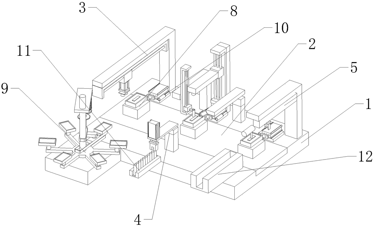
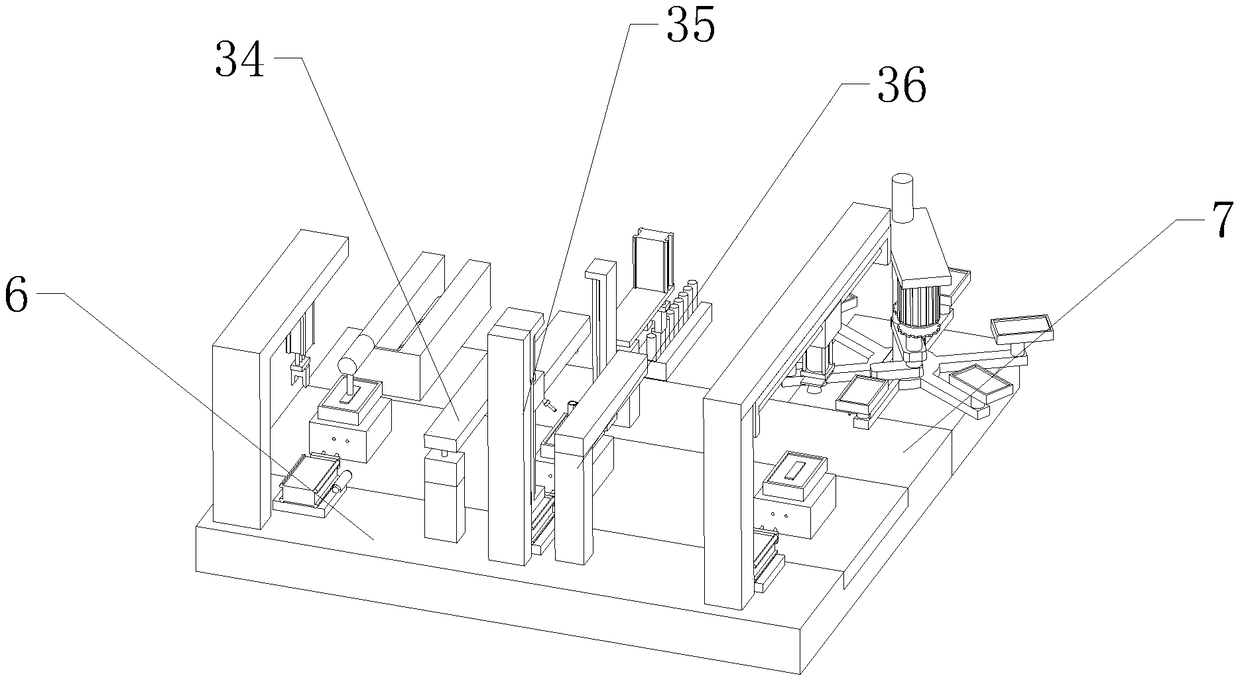
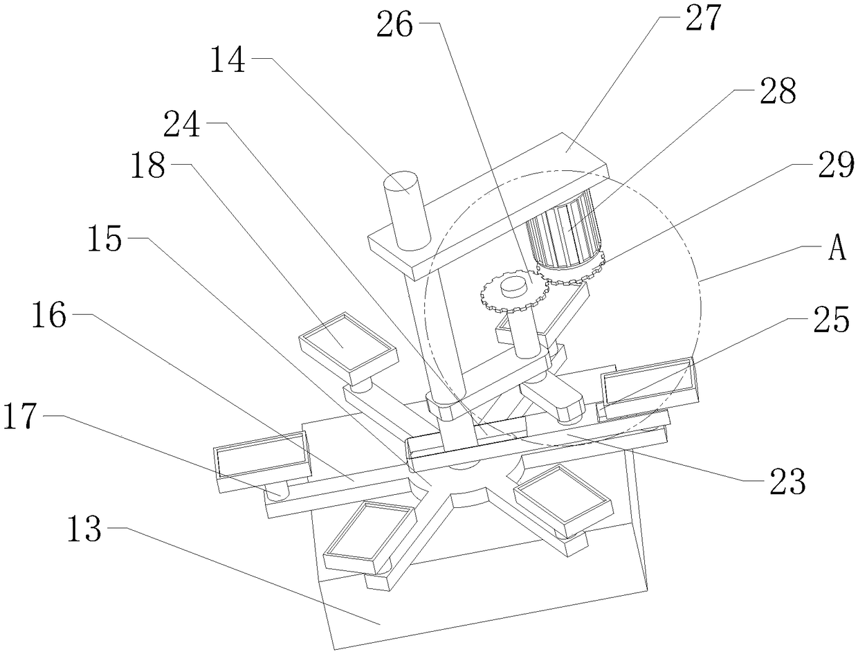
[0028] refer to Figure 1 to Figure 10 The shown automatic assembly device for finishing knives includes a workbench 1, a conveyor belt 2, a knife body assembly device, a connecting rod assembly device, and a handle assembly device 5. The conveyor belt 2 is arranged in the middle of the workbench 1, and the workbench 1 It includes a left guide platform 6 and a right guide platform 7 arranged on both sides of the conveyor belt 2, and a plurality of jig devices 8 are evenly distributed on the conveyor belt 2. The cutter body assembly device includes a cutter body feeding device 9 and a cutter body Material conveying device 3, described cutter body feeding device 9 is arranged on the side of right guide platform 7, and cutter body conveying device 3, connecting rod assembly device and handle assembly device 5 are arran...


PUM


Abstract

The invention relates to the field of automatic assembly devices, in particular to an automatic polishing cutter assembly device. The automatic polishing cutter assembly device comprises a workbench,a conveying belt, a cutter body assembling device, a connecting rod assembling device and a handle assembling device; the conveying belt is arranged in the middle position of the workbench; the workbench comprises a left guide table and a right guide table which are arranged on the two sides of the conveying belt; a plurality of jig devices are uniformly distributed on the conveying belt; the cutter body assembling device comprises a cutter body charging device and a cutter body conveying device; the cutter body charging device is arranged at the side part of the right guide table; the cutterbody conveying device, the connecting rod assembling device and the handle assembling device are sequentially arranged on the left guide table; locating devices are arranged at the side parts of the jig devices; and a connecting rod conveying rail and a handle conveying rail are arranged on the side parts of the connecting rod assembling device and the handle assembling device respectively. The assembly efficiency of a polishing cutter is improved greatly.

Description

technical field [0001] The invention relates to the field of automatic assembly devices, in particular to an automatic assembly device for a finishing knife. Background technique [0002] In the construction engineering industry, it is often necessary to lighten the wall or the ground after applying cement to the wall or the ground, that is, to smooth the uneven parts of the wall or the ground so that the entire wall or the ground appears In a smooth state, the function of the light-receiving knife is to quickly collect light on the wall or the ground. However, due to the special shape of the light-receiving knife, assembly is not convenient. Therefore, this device is invented to improve the assembly efficiency of the light-receiving knife. Contents of the invention [0003] The object of the present invention is to provide an automatic assembly device for finishing knives in view of the deficiencies in the prior art. The problem of low assembly efficiency of the finishin...

Claims


Application Information

Patent Timeline
Patent Type & Authority Applications(China)
IPC IPC(8): B23P21/00
CPCB23P21/006
Inventor 王荣铭
Owner 北京中兴卓越科技有限公司
Why Eureka
Try Eureka