Auto-pressing jig apparatus for pressing electrode lead to busbar

A bus bar and fixture technology, which is applied in the field of automatic press fixture equipment, can solve the problems of increasing product failure, reducing the joint area of ​​electrode leads and bus bar, reducing the joint strength, etc., and achieving the effect of improving welding quality

A bus bar and fixture technology, which is applied in the field of automatic press fixture equipment, can solve the problems of increasing product failure, reducing the joint area of ​​electrode leads and bus bar, reducing the joint strength, etc., and achieving the effect of improving welding quality

CN111448685AActive Publication Date: 2020-07-24LG ENERGY SOLUTION LTD

Image

  • Auto-pressing jig apparatus for pressing electrode lead to busbar
  • Auto-pressing jig apparatus for pressing electrode lead to busbar
  • Auto-pressing jig apparatus for pressing electrode lead to busbar

Examples


Embodiment Construction

[0039] Hereinafter, preferred embodiments of the present disclosure will be described in detail with reference to the accompanying drawings. Before the description, it should be understood that the terms used in the specification and appended claims should not be construed as limited to the ordinary and dictionary meanings, but based on the principle of allowing the inventor to define the terms appropriately to obtain the best interpretation Meanings and concepts corresponding to the technical aspects of the present disclosure are explained. Therefore, the descriptions presented herein are preferred examples for illustrative purposes only, and are not intended to limit the scope of the present disclosure, so it should be understood that other equivalents and Revise.

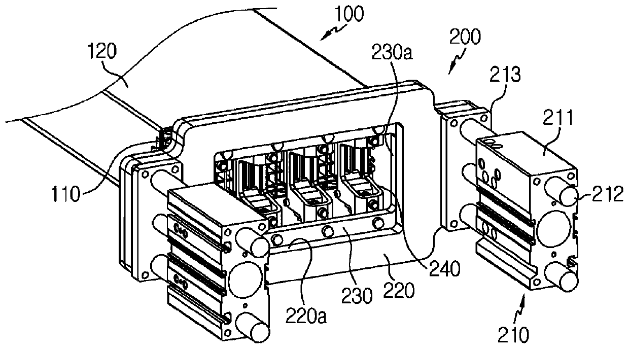
[0040] First, refer to Figure 3 to Figure 5 The overall configuration of a system for manufacturing a battery module according to an embodiment of the present disclosure is described.

[0041] image 3 is a ...


PUM


Abstract

An auto-pressing jig apparatus according to an embodiment of the present invention is a pressing jig apparatus configured to press a busbar, which is provided in a battery module, and a lead assemblyto each other, the auto-pressing jig apparatus comprises a plurality of pressing units which press each of a plurality of busbars provided in the battery module simultaneously, and press an end portion of the lead assembly from an upper portion of the busbars such that the lead assembly does not protrude to a surface of the busbars; a support plate which is connected to an end portion at one sideof the pressing units to support the plurality of pressing units; and a distance adjustment unit which is connected to the support plate to enable the support plate to flow, such that the plurality ofpressing units move away from or close to the battery module.

Description

technical field [0001] The present disclosure relates to an automatic pressing jig apparatus for closely attaching electrode leads to bus bars, and more particularly, to an automatic press jig apparatus for simultaneously closely attaching electrode lead assemblies of a plurality of battery cell stacks to bus bars. Press the clamp. [0002] This application claims priority from Korean Patent Application No. 10-2018-0075762 filed in Korea on June 29, 2018, the disclosure of which is incorporated herein by reference. Background technique [0003] In a conventional battery module, a bus bar is used to electrically connect stacked battery cells to each other, and a plurality of electrode leads respectively drawn from a plurality of battery cells are bent and positioned on the bus bar, followed by welding. [0004] When manufacturing a battery module in this way, in a state where the bent electrode leads are positioned on the bus bars, the electrode leads are closely attached to...

Claims


Application Information

Patent Timeline
24 Jul 2020
Publication
CN111448685A
IPC
H01M2/20; H01M2/26; B23K37/04; B23K101/38; H01M50/50; H01M50/505; H01M50/516
CPC
B23K37/04; H01M50/50; H01M10/04; H01M50/536; H01M50/54; H01M50/516; H01M50/505; Y02E60/10
Inventors
金炅模; 文祯晤