
Box beam welding equipment and welding method

A technology for welding equipment and box beams, applied in welding equipment, welding equipment, auxiliary welding equipment, etc., can solve the problems of uneven technical level of welding personnel, great physical and mental injury of welding personnel, and inability to guarantee welding quality, and achieves a high level of improvement. Weld quality, reduced damage, tight weld results

Inactive Publication Date: 2018-11-16
GUANGZHOU WENCHONG SHIPYARD CO LTD +1
View PDF13 Cites 1 Cited by
  • Summary
  • Abstract
  • Description
  • Claims
  • Application Information

AI Technical Summary

Problems solved by technology

Due to the uneven technical level of welding personnel, it is easy to cause the following problems: 1) The weld seam is not beautiful; 2) The welding quality cannot be guaranteed; 3) The welding efficiency is not high; 4) Long-term repetitive welding will cause great physical and mental harm to the welding personnel

Method used


Image

  • Box beam welding equipment and welding method
  • Box beam welding equipment and welding method
  • Box beam welding equipment and welding method

Examples


Embodiment 1

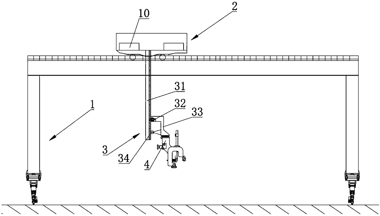
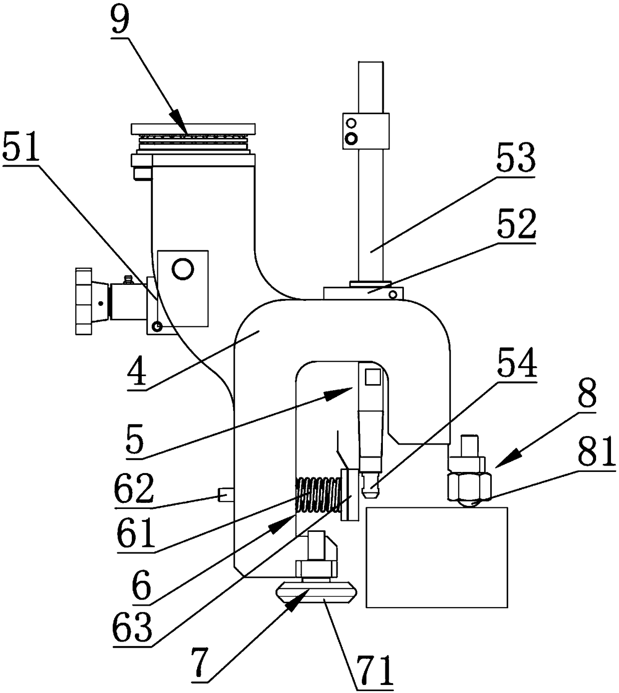
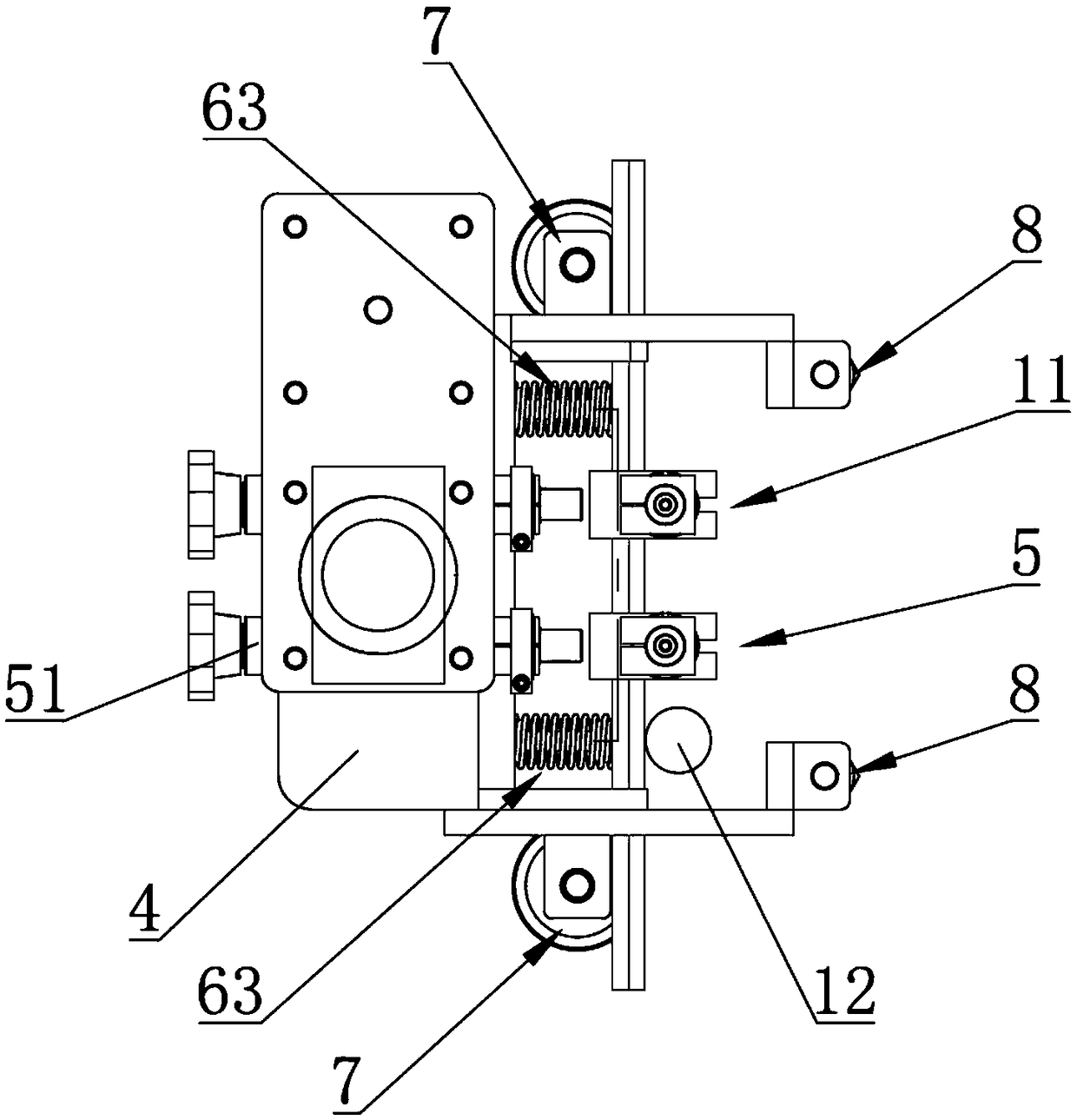
[0032] refer to Figure 1 ~ Figure 3 , the present embodiment provides a box girder welding equipment, including sequentially connected X-axis moving device 1, Y-axis moving device 2, Z-axis moving device 3, mounting frame 4 and installed on the mounting frame 4 for box-shaped The welding device 5 for beam welding, the mounting frame 4 is equipped with a baffle plate 63 assembly 6 for welding the box girder side plate and the panel, the welding device 5 is arranged on one side of the baffle plate 63 assembly 6, and the mounting frame 4 is installed There is a first pressure measuring component 7 for measuring the pressure on the side plate of the box girder in contact with the panel and a second pressure measuring component 8 for measuring the pressure on the side plate of the box girder in contact with the side plate, and the Y-axis moving device 2 is set There is a welding wire feeding device 10 for feeding welding wire to the welding device 5; it also includes a control dev...

Embodiment 2

[0050] refer to Figure 4 , The difference between this embodiment and Embodiment 1 is that the X-axis moving device 1 is not included, and the number of other devices is two groups, and the two sides of the box girder are welded at the same time to improve the welding efficiency.


PUM


Abstract

The invention relates to the technical field of welding and particularly relates to box beam welding equipment. The box beam welding equipment comprises an X-axis moving device, a Y-axis moving device, a Z-axis moving device, a mounting frame and a welding device, wherein the X-axis moving device, the Y-axis moving device, the Z-axis moving device, the mounting frame and the welding device are connected sequentially; the welding device is installed at the mounting frame; a baffle component is installed at the mounting frame; the welding device is arranged at one side of the baffle component; afirst pressure measuring component and a second pressure measuring component are installed at the mounting frame; the Y-axis moving device is provided with a welding wire conveying device; the box beam welding equipment further comprises a control device; the control device is correspondingly electrically connected with the X-axis moving device, the Y-axis moving device, the Z-axis moving device,the welding device and the welding wire conveying device; and the first pressure measuring component is electrically connected with the second pressure measuring component. Besides, the invention further provides a box beam welding method, the welding efficiency and quality is improved, and injuries of a welding worker are reduced.

Description

technical field [0001] The invention relates to the technical field of design welding, in particular to a box girder welding equipment and a welding method. Background technique [0002] The length of the box girder can reach 20 meters, and the width and height can reach 2 to 3 meters. Because of its closed thin-walled section, it has the advantages of high torsional rigidity and beautiful appearance. It is mainly used in steel structure bridge construction, large-scale factory building construction and other projects. [0003] For now, after the large box girder is assembled, the four regular welds consisting of the cover plate, web plate, and bottom plate are welded by hand or with auxiliary welding equipment. Due to the uneven technical level of welding personnel, it is easy to cause the following problems: 1) The weld seam is not beautiful; 2) The welding quality cannot be guaranteed; 3) The welding efficiency is not high; 4) Long-term repetitive welding will cause great...

Claims


Application Information

Patent Timeline
Patent Type & Authority Applications(China)
IPC IPC(8): B23K37/00B23K37/02B23K37/04B23K31/02
CPCB23K31/02B23K37/00B23K37/0211B23K37/0252B23K37/0443
Inventor 邹福顺翁耿贤罗兴民徐朝阳郑辉林阳峰涂源根陈世明
Owner GUANGZHOU WENCHONG SHIPYARD CO LTD
Learn More