Light-emitting diode

A technology for light-emitting diodes and ceramic substrates, applied in the field of lighting, can solve the problems of easy formation of gaps, poor air tightness and reliability of devices, and large local stress, so as to avoid gap problems and ensure the air tightness and reliability of packages.

Active Publication Date: 2018-08-17
SHANGHAI UNIV
View PDF5 Cites 1 Cited by
  • Summary
  • Abstract
  • Description
  • Claims
  • Application Information

AI Technical Summary

Problems solved by technology

On the one hand, epoxy resin is prone to aging under the conditions of ultraviolet light and high temperature, which affects the airtightness and light extraction efficiency of LED packaging.
On the other hand, laser packaging is usually directly packaged with glass paste, or a metal layer is plated between the cover plate and the substrate, but the process of plating a metal layer on the surface of the ceramic substrate and glass cover plate is complicated and costly, and the metal layer The bonding force with the ceramic substrate and glass cover is poor, and it is easy to fall off, which affects the airtightness and reliability of the device
Moreover, due to the roughness of the surface of the ceramic substrate and the existence of many voids, direct use of glass paste to realize the bonding of the ceramic substrate and the glass cover plate is easy to form voids, and the uneven distribution of the glass paste will also cause excessive local stress. Large, resulting in poor airtightness and reliability of the device

Method used


Image

  • Light-emitting diode

Examples


Embodiment Construction

[0023] The following will clearly and completely describe the technical solutions in the embodiments of the present invention with reference to the accompanying drawings in the embodiments of the present invention. Obviously, the described embodiments are only some, not all, embodiments of the present invention. Based on the embodiments of the present invention, all other embodiments obtained by persons of ordinary skill in the art without making creative efforts belong to the protection scope of the present invention.

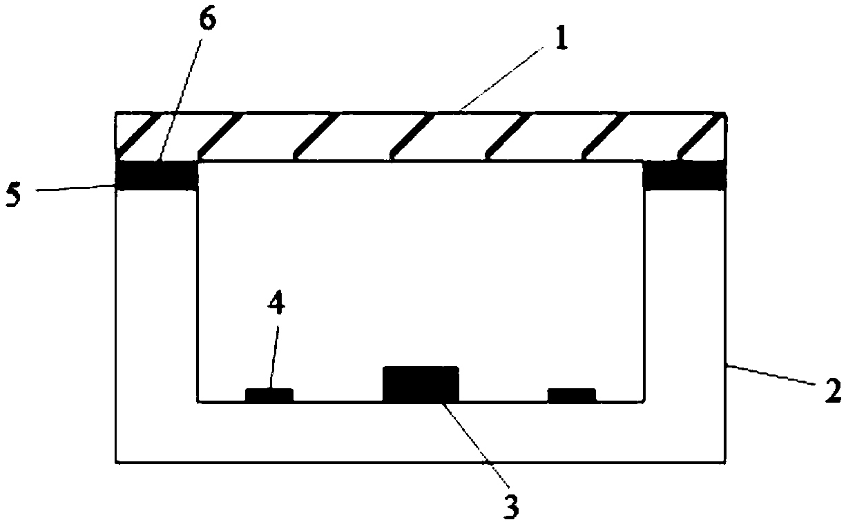
[0024] The purpose of the present invention is to provide a light-emitting diode. A smooth glaze layer is made on the surface of the ceramic substrate, and the glass paste is used to realize the low-temperature tight welding of the glass cover plate and the ceramic substrate, which reduces the complexity of the process and improves the luminescence. Diode packaging hermeticity and reliability.

[0025] In order to make the above objects, features and advantage...


PUM

PropertyMeasurementUnit
radiusaaaaaaaaaa
radiusaaaaaaaaaa
refractive indexaaaaaaaaaa

Abstract

The invention discloses a light-emitting diode. The light-emitting diode comprises a glass cover plate, a ceramic substrate, a light-emitting diode chip and a circuit structure layer. The ceramic substrate is provided with a groove. The shape of the glass cover plate is matched with the shape of the groove, and the glass cover plate covers the groove. The contact surface of the ceramic substrate and the glass cover plate is provided with a glaze layer. The contact surface of the glass cover plate and the groove is provided with a glass paste layer. The glass paste layer is used for welding theglass cover plate and the ceramic substrate together in a fusion way. The light-emitting diode chip is arranged in the groove, and the light-emitting diode chip is connected with the circuit structure layer. According to the light-emitting diode, the smooth glaze layer is manufactured on the surface of the ceramic substrate, and low temperature compact fusion welding of the glass cover plate andthe ceramic substrate is realized by using the glass paste so that the process complexity can be reduced, and the packaging air tightness and the reliability of the light-emitting diode can be enhanced.

Description

technical field [0001] The invention relates to the lighting field, in particular to a light emitting diode. Background technique [0002] Most of the existing LED lamps are packaged with epoxy resin and laser. On the one hand, epoxy resin is prone to aging under the conditions of ultraviolet light and high temperature, which affects the airtightness of LED packaging and light extraction efficiency. On the other hand, laser packaging is usually directly packaged with glass paste, or a metal layer is plated between the cover plate and the substrate, but the process of plating a metal layer on the surface of the ceramic substrate and glass cover plate is complicated and costly, and the metal layer The bonding force with the ceramic substrate and the glass cover is poor, and it is easy to fall off, which affects the airtightness and reliability of the device. Moreover, due to the roughness of the surface of the ceramic substrate and the existence of many voids, direct use of ...

Claims


Application Information

Patent Timeline
Patent Type & Authority Applications(China)
IPC IPC(8): H01L33/48H01L23/10
CPCH01L2924/16195H01L33/48H01L23/10
Inventor 李春亚王毅斌胡雅萌殷录桥张建华
Owner SHANGHAI UNIV
Why Eureka
Try Eureka