Supercharge Your Innovation With Domain-Expert AI Agents!

Pressurizing washing equipment

A technology for cleaning equipment and chambers, which is applied to metal processing equipment, used abrasive processing devices, abrasives, etc., can solve problems such as low cleaning efficiency, damage, and uneven force on contact points, so as to achieve low impact of human factors, Reduce scrap and uniform force effect

Pending Publication Date: 2018-12-11
北京亦盛精密半导体有限公司
View PDF0 Cites 0 Cited by
  • Summary
  • Abstract
  • Description
  • Claims
  • Application Information

AI Technical Summary

Problems solved by technology

[0002] Semiconductor parts are brittle materials. After some types of parts are processed, there are hundreds or even thousands of small holes or special-shaped holes on them. The existing dredging and cleaning techniques are mostly air guns, high-pressure water guns or drill bits and hard objects. After dredging, use ultrasonic or chemical agents to clean. Because of the hydrophobic nature of semiconductor materials, air chambers will be generated when there is no gravity or pressure in small holes or special-shaped holes and gaps, resulting in the inability of chemical agents or water to circulate in the holes, thus failing to achieve cleaning. parts requirements
Moreover, brittle materials will have problems such as cracks, chipping, and damage under the condition of local uneven pressure. The existing technology is to clamp the parts on the fixture, and clean the holes of the parts one by one through manual operation. The pressure of the point will be uneven, and the cleaning efficiency will be low
In the process of parts cleaning, due to the uncontrollability of human operation, the cleanliness of the parts is uncontrollable, resulting in the parts failing to meet the cleaning requirements. When manually dredging small holes or special-shaped holes one by one, it is easy to damage the surface integrity. Due to the material characteristics of the parts, the inner wall of the aperture will also be damaged, which will result in long processing time and low efficiency, and the parts will be scrapped due to the uncertainty of manual operation.

Method used


Image

  • Pressurizing washing equipment
  • Pressurizing washing equipment

Examples


Embodiment Construction

[0023] The present invention and the technical solutions in the embodiments of the present invention will be clearly and completely described below in conjunction with the accompanying drawings.

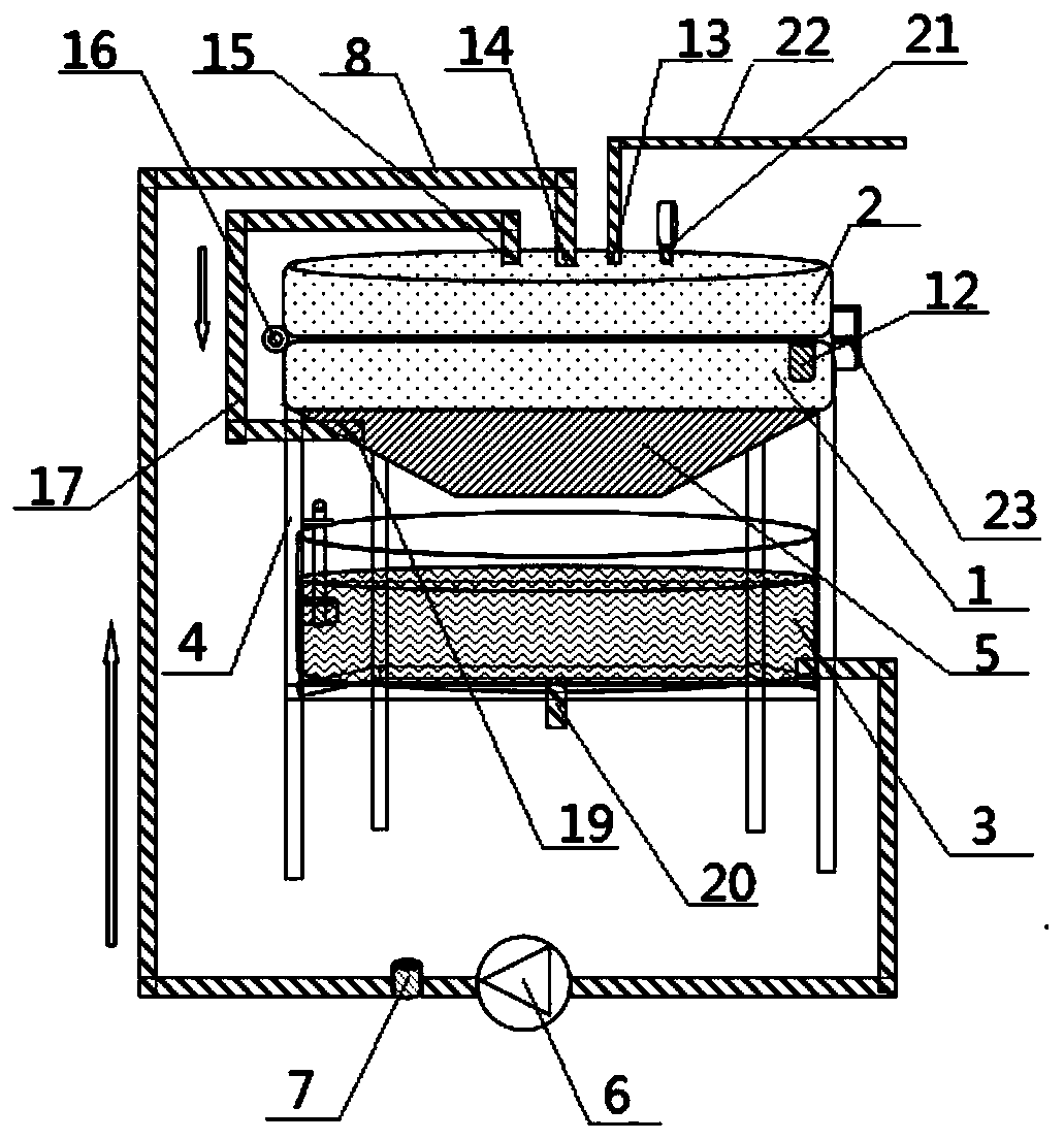
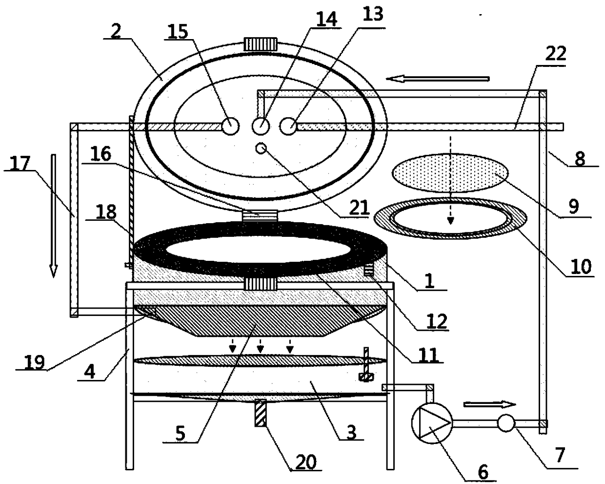
[0024] Such as Figure 1-2 As shown, a pressurized cleaning device includes an upper cavity 2 and a lower cavity 1, wherein:

[0025] The lower cavity is arranged on the bracket 4, and the upper cavity 2 is hinged and fastened to the lower cavity 1 by a hinge 16 to form a sealed space. The top of the upper cavity 2 is provided with an air inlet 13 and a water inlet 14, and the air inlet 13 is connected to the inlet. The air pipe 22 and the water inlet 14 are connected to the water inlet pipe 8; the bottom of the lower chamber 1 is provided with a ventilation hole;

[0026] The sealed space is provided with an annular tooling 10, and the inner circumference of the annular tooling 10 is provided with an annular step for placing the circular part 9, and the annular tooling 10 is horizo...


PUM


Abstract

The invention discloses pressurizing washing equipment. The pressurizing washing equipment comprises an upper cavity and a lower cavity, wherein the upper cavity is hinged and buckled to the lower cavity through a hinging part to form a sealed space; an air inlet and a water inlet are formed in the top of the upper cavity; the air inlet is connected with an air inlet pipe; the water inlet is connected with a water inlet pipe; an air vent is formed in the bottom of the lower cavity; an annular tool is arranged in the sealed space; an annular step is peripherally arranged in the annular tool; acollection groove is formed below the lower cavity. According to the washing equipment disclosed by the invention, a part can be placed on the annular tool with the step and the annular tool is buckled on an annular clamping groove in the sealed space of the washing equipment; then a washing medium is added into the sealed space from the top of the sealed space under the action of pressurizing; the medium passes through a small hole or an abnormal-shaped hole and a gap on the part, so that the effect of washing the part under a balanced pressing condition is realized; uniform stress can be ensured when the part is washed and abandonment is reduced; meanwhile, the washing efficiency is improved and anthropic factor influences are minimized.

Description

technical field [0001] The invention belongs to the technical field of semiconductor material cleaning equipment, and in particular relates to a pressurized cleaning equipment. Background technique [0002] Semiconductor parts are brittle materials. After some types of parts are processed, there are hundreds or even thousands of small holes or special-shaped holes on them. The existing dredging and cleaning techniques are mostly air guns, high-pressure water guns or drill bits and hard objects. After dredging, use ultrasonic or chemical agents to clean. Because of the hydrophobic nature of semiconductor materials, air chambers will be generated when there is no gravity or pressure in small holes or special-shaped holes and gaps, resulting in the inability of chemical agents or water to circulate in the holes, thus failing to achieve cleaning. parts requirements. Moreover, brittle materials will have problems such as cracks, chipping, and damage under the condition of local ...

Claims


Application Information

Patent Timeline
IPC IPC(8): B24C3/32B24C9/00
CPCB24C3/32B24C9/00
Inventor 吴明庆袁林锋
Owner 北京亦盛精密半导体有限公司
Features
  • R&D
  • Intellectual Property
  • Life Sciences
  • Materials
  • Tech Scout
  • Unparalleled Data Quality
  • Higher Quality Content
  • 60% Fewer Hallucinations
Learn More