Robot anti-collision device

An anti-collision device and robot technology, applied in the field of robots, can solve problems such as collapse damage and robot damage, and achieve the effects of improving impact buffering, good impact resistance, and high strength and toughness

Inactive Publication Date: 2018-12-11
安徽爱依特科技有限公司
View PDF14 Cites 11 Cited by
  • Summary
  • Abstract
  • Description
  • Claims
  • Application Information

AI Technical Summary

Problems solved by technology

[0002] The robot is controlled by the operator, and sometimes it is unavoidable to suffer strong impacts when the operation is wrong. Traditional robots have less design on the anti-collision protection at the bottom. After the bottom is hit, it is difficult to maintain balance and collapse and damage. For example, the application number is CN201711350534 .7 A robot anti-collision protection type base, comprising a base body, the bottom of the base body is provided with a roller body, and an anti-collision protection belt is arranged on the outer end surface of the base body, and an anti-collision protection belt is arranged on the anti-collision protection belt. There are a plurality of toggle pulleys, and a plurality of convex pads are arranged on the side end surface of the base body, and a plurality of rotating shaft vertical rods are arranged at the same distance on the anti-collision protection belt, and the toggle pulleys are horizontally installed and set on the On the vertical rod of the rotating shaft, the anti-collision protection belt protrudes and is installed on the middle section of the outer end surface of the base body. The base body is a cylindrical seat body or a square seat body, and the anti-collision protection belt is made of aluminum alloy. The bump pad is made of elastic rubber
[0003] The protection structure of the above-mentioned robot protective base is relatively simple. When encountering more severe impacts, or after suffering multiple impacts, the setting of the protective belt of the ring device is difficult to withstand and resist such impacts, which may easily cause damage to the robot. Therefore, a It is necessary to solve the above-mentioned problems with robot anti-collision devices

Method used


Image

  • Robot anti-collision device
  • Robot anti-collision device
  • Robot anti-collision device

Examples


Embodiment Construction

[0019] The following will clearly and completely describe the technical solutions in the embodiments of the present invention with reference to the accompanying drawings in the embodiments of the present invention. Obviously, the described embodiments are only some, not all, embodiments of the present invention. Based on the embodiments of the present invention, all other embodiments obtained by persons of ordinary skill in the art without making creative efforts belong to the protection scope of the present invention.

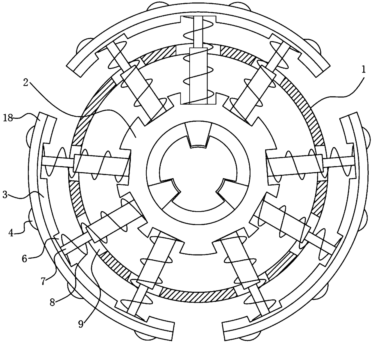
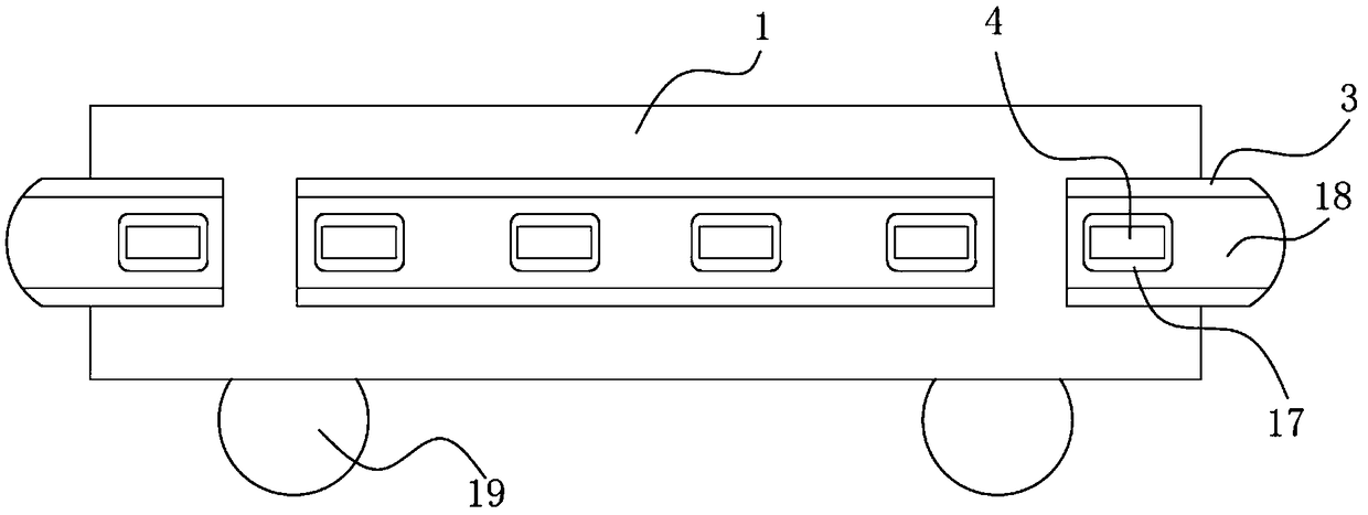
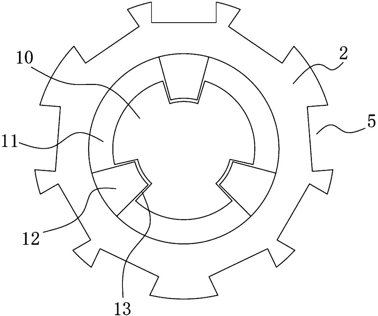
[0020] see Figure 1-4 The present invention provides a technical solution: a robot anti-collision device, including a chassis 1, a support seat 2 is installed inside the chassis 1, a support plate 3 is provided on the outside of the chassis 1, and a support plate 3 is installed on the outside of the support plate 3 Anti-collision wheel 4, a first groove 5 is formed on the outside of the support seat 2, a second groove 6 is formed on the inside of the support ...


PUM


Abstract

The invention discloses a robot anti-collision device. The device comprises a chassis, a supporting seat is arranged in the chassis, supporting plates are arranged on the outer side of the chassis, anti-collision wheels are arranged on the outer side of the supporting plates, first grooves are formed in the outer side of the supporting seats, second grooves are formed in the inner side of the supporting plates, buffer devices are fixedly connected between the first grooves and the second grooves, first springs sleeves the outer side of the buffer device, the two ends of the first springs are connected to the bottom of the first grooves and the bottom of the second grooves respectively, the middle of the interior of the chassis is fixedly connected with a fixing seat, clamping grooves are formed in the outer side of the fixing seat. The device is novel in structure and is arranged through the supporting plate, the supporting seat, the buffer device and the first springs, so that the supporting plate firstly touches the collided object when the chassis collides with the outside, the device is arranged through the first springs and the buffer device, so that two layers of buffering can be carried out on the supporting plate, and the effect of buffering impact force of the supporting plate is improved.

Description

technical field [0001] The invention relates to the technical field of robots, in particular to a robot anti-collision device. Background technique [0002] The robot is controlled by the operator, and sometimes it is unavoidable to suffer strong impacts when the operation is wrong. Traditional robots have less design on the anti-collision protection at the bottom. After the bottom is hit, it is difficult to maintain balance and collapse and damage. For example, the application number is CN201711350534 .7 A robot anti-collision protection type base, comprising a base body, the bottom of the base body is provided with a roller body, and an anti-collision protection belt is arranged on the outer end surface of the base body, and an anti-collision protection belt is arranged on the anti-collision protection belt. There are a plurality of toggle pulleys, and a plurality of convex pads are arranged on the side end surface of the base body, and a plurality of rotating shaft vertic...

Claims


Application Information

Patent Timeline
Patent Type & Authority Applications(China)
IPC IPC(8): B25J19/06
CPCB25J19/06
Inventor 徐平谢骞王昆仑
Owner 安徽爱依特科技有限公司
Why Eureka
Try Eureka