Smart lock for power distribution cabinet

A technology of intelligent locks and power distribution cabinets, which is applied in the application of electric locks, building locks, locks, etc., can solve the problems of low safety, unfavorable service life, and inconvenience, so as to increase the damage rate and reduce the The effect of service life

Inactive Publication Date: 2018-12-11
南京市六合区三新供电服务有限公司
View PDF0 Cites 1 Cited by
  • Summary
  • Abstract
  • Description
  • Claims
  • Application Information

AI Technical Summary

Problems solved by technology

[0003] Most of the existing locks for power distribution cabinets use conventional traditional locks, which are not very safe. At the same time, you need to wear a key to open them, which is very inconvenient. In addition, the password input areas in the existing password smart locks are mostly exposed to the outside. It is easily damaged by sunlight, which is not conducive to prolonging its service life

Method used


Image

  • Smart lock for power distribution cabinet
  • Smart lock for power distribution cabinet
  • Smart lock for power distribution cabinet

Examples


Embodiment Construction

[0020] The technical solution of this patent will be further described in detail below in conjunction with specific embodiments.

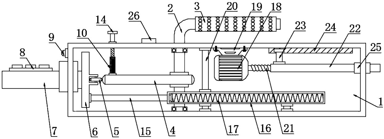
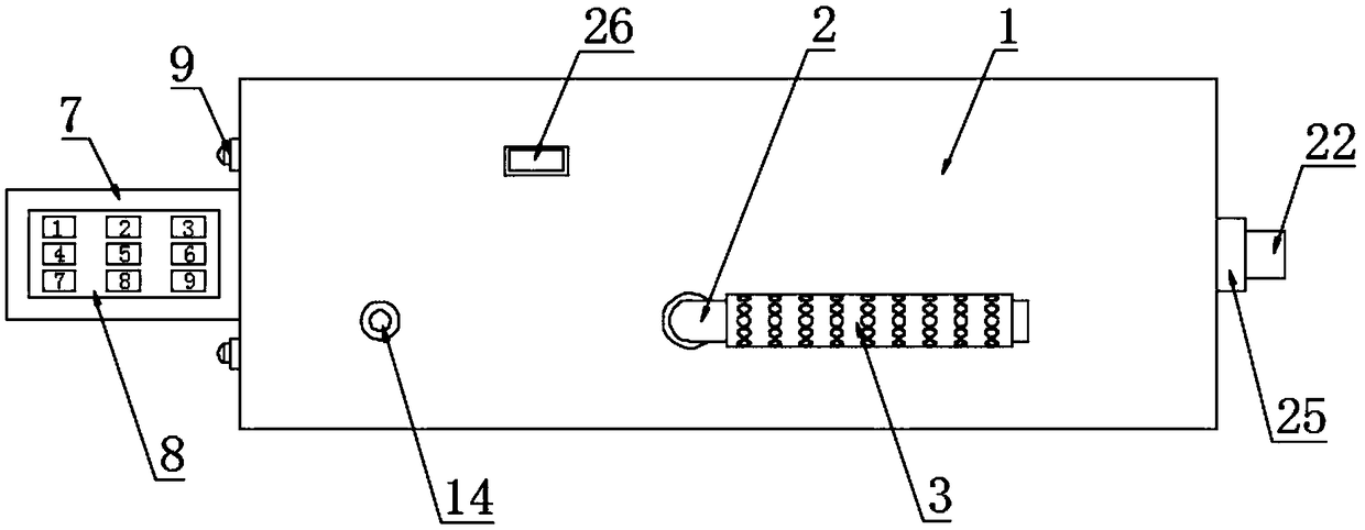
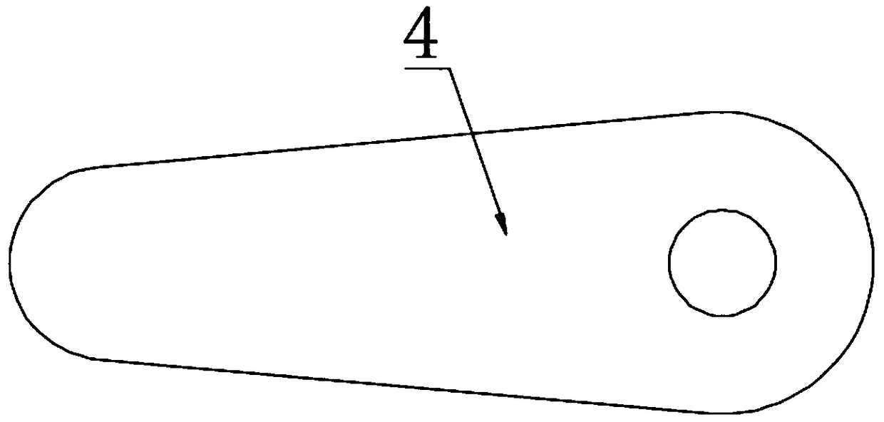
[0021] see Figure 1~4 , in an embodiment of the present invention, a smart lock for a power distribution cabinet includes a smart lock body 1, a cam 4, a telescopic plate 7, a sleeve rod 12, a pull rod 15, a servo motor 18, a screw rod 21 and a guide groove 24; The upper part of the lock body 1 is provided with a rotating shaft 2, and the upper part of the rotating shaft 2 is covered with a handle 3. The surface of the handle 3 is equidistantly distributed with a plurality of ventilation holes. The handle 3 is made of soft rubber material, and the rotating shaft 2 passes through the smart lock body 1 and It is rotationally connected with the bearing, and the lower part of the rotating shaft 2 is fixedly connected to the cam 4. The handle 3 made of soft rubber reduces the direct contact between the palm and the rotating shaft 2, causing discomfort....


PUM


Abstract

The invention discloses a smart lock for a power distribution cabinet. The lower portion of a rotating shaft is fixedly connected with a cam, the left side of the cam abuts a small rotating wheel, thesmall rotating wheel is rotatably connected witha movable plate, the center of the left side end surface of the movable plate is fixedly connected with atelescopic plate, a strip-shaped through-holeis formed in the left side of a smart lock body, the telescopic plate is slidably connected to the strip-shaped through-hole,the upper surface of the telescopic plate is fixedly connected to a keyboard, the lower portion of the movable plate is fixedly connected to a pull rod, the right side of the pull rod is sleeved witha second sleeve, and the inside of the second sleeve is provided with a second spring. The smart lock drives the rotating shaft and the cam to rotate by rotating the handle, the cam drives the movable plate to move to the left, the movable plate drives the keyboard to be pushed out from the inside of asmart lock body, the upper end of a sleeve rod is aligned with a round hole, the sleeve rod pushes up a top rod to make a button protrude so as tokeep the cam still, it is convenient to input a password, when the button is pressed to separate the sleeve rod from the round hole, the pull rod and the movable plate are driven to move to the right by the action of the secondspring to place the keyboard, and the case that the long-term exposure of the keyboard increases the damage rate and reduces the service life is avoided.

Description

technical field [0001] The invention relates to an intelligent lock, in particular to an intelligent lock for a power distribution cabinet. Background technique [0002] Smart locks refer to locks that are more intelligent in terms of user identification, security, and management, which are different from traditional mechanical locks. Smart lock is the execution part of locking the door in the access control system. The current smart lock is divided into two types: fingerprint scanning and password. The scanning method is very simple. Just put your finger on the top of the scanning place and scan from top to bottom. You don’t need to press your finger on the scanning place, and the scanning method reduces fingerprint residue. , greatly reducing the possibility of fingerprints being copied, safe and exclusive. The unlocking method of the password lock is simpler, and the unlocking can be realized by entering the password, so as to avoid the problem of multiple scanning due ...

Claims


Application Information

Patent Timeline
Patent Type & Authority Applications(China)
IPC IPC(8): E05B65/52E05B47/00E05B49/00E05B17/10
CPCE05B65/02E05B17/10E05B47/0012E05B49/00
Inventor 李光亮余存瑞郑杰柏建荣张爱民王久龙郭永陆
Owner 南京市六合区三新供电服务有限公司
Why Eureka
Try Eureka