Oil field water injection well high pressure multi-purpose nipple

An oilfield water injection and multi-purpose technology, applied in wellbore/well components, wellbore/well valve devices, measurement, etc., can solve the problems of water injection wells that cannot record oil casing pressure, cannot detect oil casing pressure, and are difficult to replace , to achieve the effect of overcoming the problem of pipeline pressure admission, high-efficiency pipeline pressure admission, and low device cost

Active Publication Date: 2022-04-26
彭继伟
View PDF0 Cites 0 Cited by
  • Summary
  • Abstract
  • Description
  • Claims
  • Application Information

AI Technical Summary

Problems solved by technology

In the case of extreme weather in winter and the inner structure of the needle valve corroded by the water injection well, the pressure gauge is often damaged by freezing, the pressure cannot be recorded, and the needle valve often suffers from puncture leakage and poor sealing
Moreover, high water pressure often occurs when the valve is punctured and cannot be replaced, which makes the pressure recording work of the water injection well unable to proceed normally. In addition, when replacing the valve or pressure gauge that is not tightly sealed in winter, there is a great safety hazard, and sometimes the pressure is overpressured, causing damage to the equipment Damaged, high replacement cost
[0003] Specifically, in the process of using the needle valve in the prior art in winter, there are often problems of puncture leakage, failure to close, and difficulty in replacement, and the problem rate is about 2 / 3; the use of the pressure gauge in winter, the pressure gauge 30MPA ordinary pressure gauge, the spring tube is often frozen and deformed in winter, the pressure gauge is damaged, and the problem rate is 7 / 10; the oil casing pressure cannot be recorded, and the oil casing pressure cannot be recorded for the water injection well, resulting in the lack of technical data, and the needle type is replaced in winter Valves and gauges tend to be riskier

Method used


Image

  • Oil field water injection well high pressure multi-purpose nipple

Examples


Embodiment Construction

[0019] The structural principle and working principle of the present invention will be further described in detail below in conjunction with the drawings and embodiments.

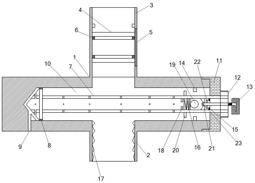
[0020] see figure 1 , oil field water injection well high-pressure multi-purpose sub, including a cross-shaped sub body 1 composed of a vertical rod body and a horizontal rod body, a piston 4 is provided in the inner cavity of the upper section of the vertical rod body, and a pressure gauge nozzle 3 is provided at the upper end of the vertical rod body; A hydraulic oil guide channel 5 is provided on the vertical rod body wall on the side where the piston 4 is running; the lower section of the vertical rod body is a needle valve joint 2; There is a hollow conical spool 7 inside, and the left end of the hollow conical spool 7 is provided with a conical head sealing ring 8; the left end of the conical valve cavity 10 is provided with a vent 9; Press cap 11; the outside of press cap 11 is provided with top scr...


PUM


Abstract

High-pressure multi-purpose nipples for water injection wells in oil fields, including a cross-shaped nipple body composed of a vertical rod body and a horizontal rod body. The inner cavity of the vertical rod body is equipped with a piston. The section is a needle valve joint; a conical valve cavity is provided in the horizontal rod body, a hollow conical valve core is provided in the conical valve cavity, and a conical head sealing ring is provided at the left end of the hollow conical valve core; the conical valve cavity There is a vent at the left end of the cone valve cavity; a pressure cap is provided at the right end of the conical valve cavity; a top screw nut is provided on the outside of the pressure cap; The inner wall of the tapered valve cavity is provided with a right limit retaining ring and a left limit retaining ring; a spring is arranged between the right limit retaining ring and the left limit retaining ring; the right end of the spring is connected with a sealing ball The rod body of the hollow venting screw passes through the top screw nut, and the left end of the rod body is connected with the top contact of the sealing ball; it has the characteristics of small size, simple structure, good sealing effect, low cost and safety.

Description

technical field [0001] This application belongs to the technical field of needle valves for oilfield water injection wells, and in particular relates to high-pressure multipurpose nipples for oilfield water injection wells. Background technique [0002] The water injection well pressure gauge used in the oil field is a 30MPA ordinary pressure gauge, and the price is about 46 yuan. The pressure taking valve connected to the pressure gauge is a needle valve with a design pressure of 25MPA, and the price is about 90 yuan. In extreme weather in winter and when the inner structure of the needle valve is corroded by the water injection well, the pressure gauge is often damaged by freezing, the pressure cannot be recorded, and the needle valve often suffers from puncture leakage and poor sealing. Moreover, high water pressure often occurs when the valve is punctured and cannot be replaced, which makes the pressure recording work of the water injection well unable to proceed normal...

Claims


Application Information

Patent Timeline
Patent Type & Authority Patents(China)
IPC IPC(8): E21B43/20E21B33/04E21B47/06E21B34/08
CPCE21B43/20E21B33/04E21B47/06E21B34/08
Inventor 龚波路斌马建华彭继伟高彦军李静方铁煜王瑞己刘峰徐林才王二营徐晶
Owner 彭继伟
Why Eureka
Try Eureka