Pressure-difference valve unit, hydraulic control system and engineering machinery

A hydraulic control system and engineering machinery technology, applied in the hydraulic field, can solve problems such as the narrowing of the controllable range, affecting the speed regulation of the system, and the deterioration of the control performance, so as to achieve good micro-movement, small flow adjustment gain, and flow adjustment big gain effect

Inactive Publication Date: 2018-12-11
ZOOMLION HEAVY IND CO LTD
View PDF2 Cites 1 Cited by
  • Summary
  • Abstract
  • Description
  • Claims
  • Application Information

AI Technical Summary

Problems solved by technology

In this case, if you continue to pull the handle, although the pressure controlled by the handle changes, the flow through the main valve does not change (it is still the flow output by the variable pump), so the actual controllable range of the handle is narrowed, and the That is to say, there is a large idle stroke in the handle, which greatly affects the speed regulation of the entire system, resulting in poor control performance of the entire system

Method used


Image

  • Pressure-difference valve unit, hydraulic control system and engineering machinery
  • Pressure-difference valve unit, hydraulic control system and engineering machinery
  • Pressure-difference valve unit, hydraulic control system and engineering machinery

Examples


Embodiment Construction

[0041] Specific embodiments of the present invention will be described in detail below in conjunction with the accompanying drawings. It should be understood that the specific embodiments described here are only used to illustrate and explain the present invention, and are not intended to limit the present invention.

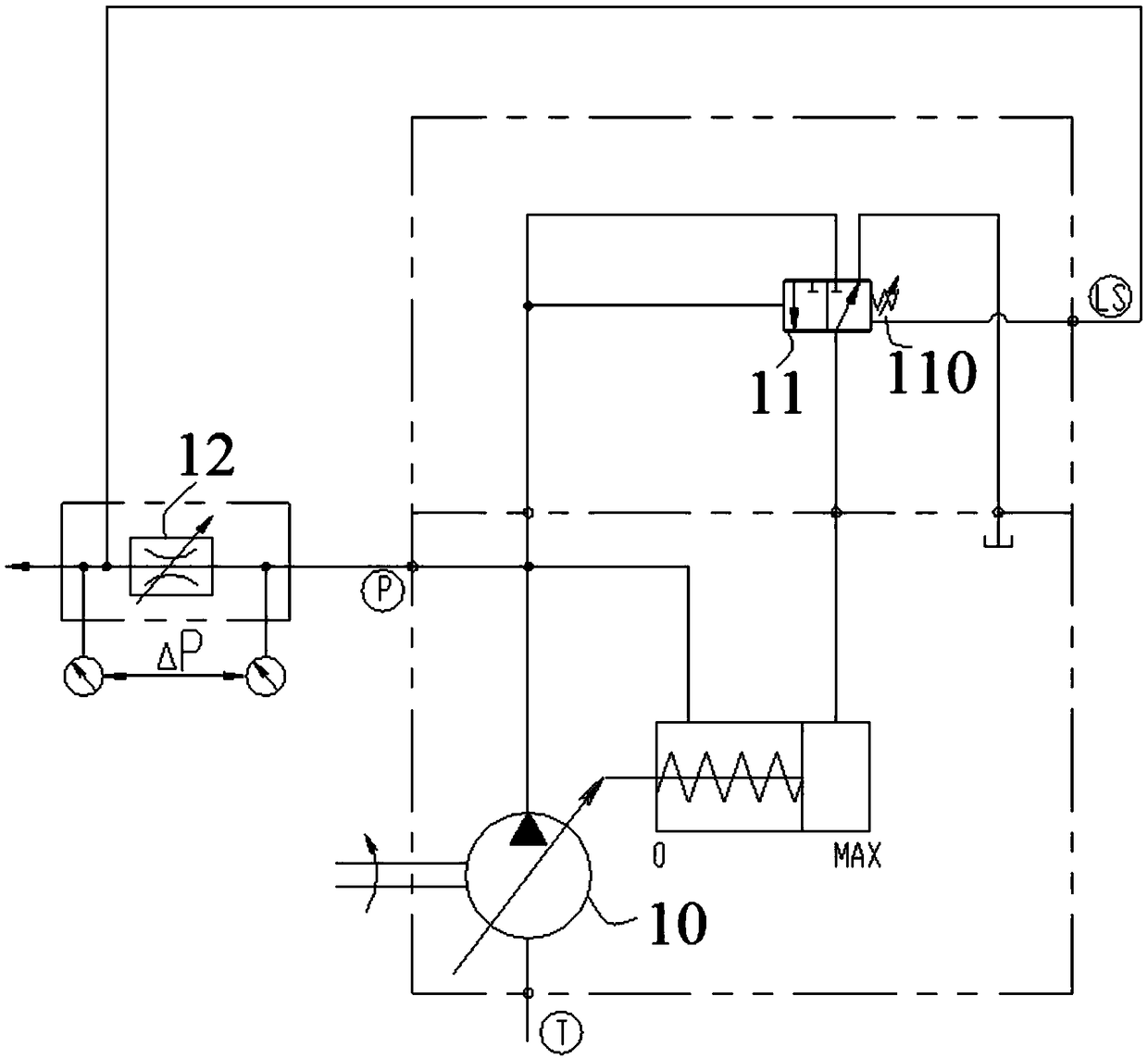
[0042] figure 1 It is a structural diagram of a hydraulic system in the prior art. The hydraulic system mainly includes: a hydraulic pump 10, a variable valve 11, a main valve 12 and the like. Wherein, the left end of the variable variable valve 11 is connected with the outlet of the hydraulic pump 10 (the pressure here is P), and its right end is connected with the spool spring 110 (the preset spring force is F 弹 ) and the load feedback oil port LS of the main valve 12 (the pressure here, that is, the load pressure is P LS ) connected. The working principle of the hydraulic pump 10 is as follows: the output flow Q of the hydraulic pump 10 is introduced into...


PUM


Abstract

The invention relates to the technical field of hydraulic pressure, and discloses a pressure-difference valve unit, a hydraulic control system and engineering machinery. The hydraulic control system comprises a hydraulic pump, a main valve, a pressure-difference valve and a controller, wherein the hydraulic pump is used for providing hydraulic oil for an actuating element under the driving effectof an engine; the main valve is used for controlling the actual output flow of the hydraulic oil from the hydraulic pump to the actuating element; the pressure-difference valve comprises a variable-quantity valve and a variable-pressure valve; a constant-pressure element is arranged at a first end of the variable-quantity valve; the variable-pressure valve is arranged at a second end of the variable-quantity valve and is used for adjusting pressure difference between the two ends of the main valve under the different rotating speeds of the engine, so that the maximum output flow of the main valve adjusted by a handle in an output flow range is equal to the output flow of the hydraulic pump; and the controller is connected with the engine and the variable-pressure valve, is used for receiving the rotating speed of the engine, and controls the output pressure of the variable-pressure valve according to the rotating speed of the engine. The whole hydraulic control system runs at high speed and meanwhile has good micro-motion performance.

Description

technical field [0001] The invention relates to the field of hydraulic technology, in particular to a differential pressure regulating valve unit, a hydraulic control system and engineering machinery. Background technique [0002] The variable pump load sensing system has good energy saving and stability, and has been widely used in truck cranes. At present, the variable pump load sensing system generally adopts the method of constant pressure difference control, and the system pressure difference ΔP is set to a higher pressure, which can ensure that all the pressure oil output by the variable pump passes through the main valve at the highest engine speed; but when the engine is idling ( or low speed), because the set pressure difference ΔP is high, when the handle is less than the full stroke, the actual flow through the main valve has reached the output flow of the idle speed (or low speed) variable pump. In this case, if you continue to pull the handle, although the pres...

Claims


Application Information

Patent Timeline
Patent Type & Authority Applications(China)
IPC IPC(8): F15B13/02B66C13/20
CPCB66C13/20F15B13/02
Inventor 谢娟萍黄珍周庆喜宋建清何伟
Owner ZOOMLION HEAVY IND CO LTD
Why Eureka
Try Eureka