a dynamic shock absorber
A dynamic vibration absorber and mass block technology, applied in vibration suppression adjustment, spring/shock absorber, non-rotational vibration suppression, etc. problems, to achieve the effect of adjustable natural frequency, wide vibration damping bandwidth, and flexible use
- Summary
- Abstract
- Description
- Claims
- Application Information
AI Technical Summary
Problems solved by technology
Method used
Image
Examples
Embodiment 1
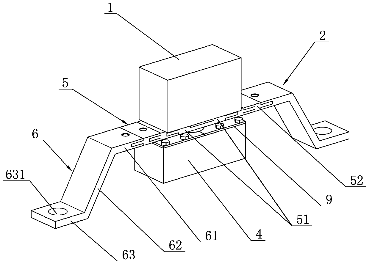
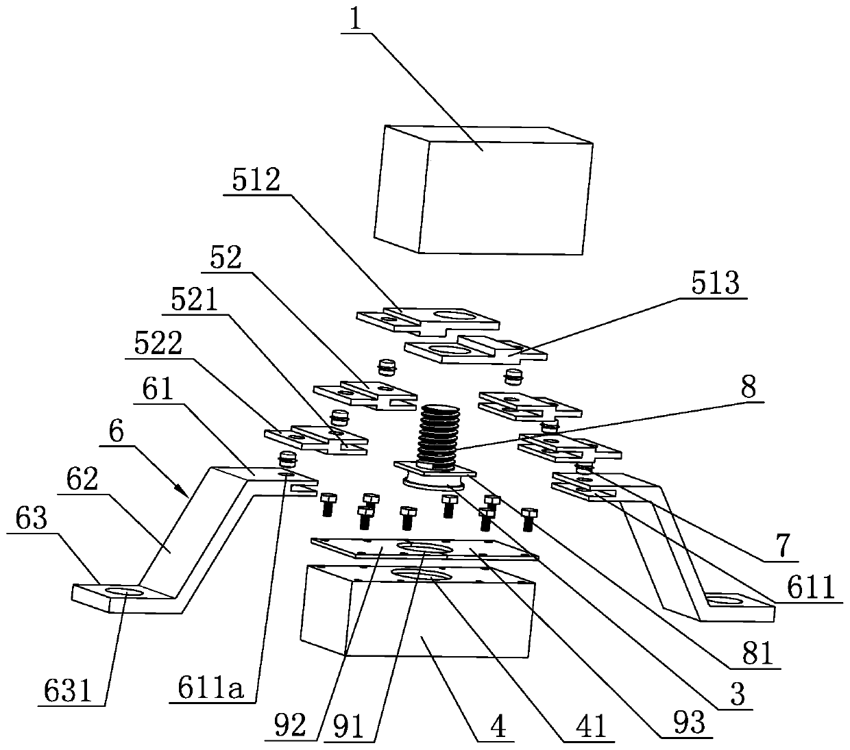
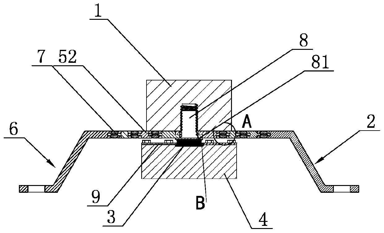
[0026] Embodiment one: if Figure 1-Figure 7 As shown, a dynamic vibration absorber includes a first vibration-absorbing assembly and a second vibration-absorbing assembly, the first vibration-absorbing assembly includes an upper mass 1 and an elastic support 2, the upper mass 1 is detachably mounted on the elastic support 2, and the second The vibration-absorbing assembly includes a rubber block 3 and a lower mass block 4, the lower mass block 4 is located in the elastic support 2, a rubber block 3 is arranged between the elastic support 2 and the lower mass block 4, and the rubber block 3 and the lower mass block 4 are detachably connected .
Embodiment 2
[0027] Embodiment two: if Figure 1-Figure 3 As shown, a dynamic vibration absorber includes a first vibration-absorbing assembly and a second vibration-absorbing assembly, the first vibration-absorbing assembly includes an upper mass 1 and an elastic support 2, the upper mass 1 is detachably mounted on the elastic support 2, and the second The vibration-absorbing assembly includes a rubber block 3 and a lower mass block 4, the lower mass block 4 is located in the elastic support 2, a rubber block 3 is arranged between the elastic support 2 and the lower mass block 4, and the rubber block 3 and the lower mass block 4 are detachably connected .
[0028] In this specific example, as Figure 4 and Figure 6As shown, the elastic bracket 2 includes a beam part 5 for installing the upper mass block 1 and a mounting part 6 fixed at both ends of the beam part 5. The mounting part 6 is used for connecting with the system to be damped, and the beam part 5 includes an intermediate conn...
Embodiment 3
[0033] Embodiment three: other parts are identical with embodiment two, and its difference is: as Figure 7 As shown, the middle connecting plate 51 includes a left connecting plate 512 and a right connecting plate 513, wherein a first connecting arm 511 is fixedly connected with one end of the left connecting plate 512, and the other end of the left connecting plate 512 is equipped with a locking arm 5121, and the upper locking arm 5121 is provided with an upper through hole 5121a matched with the screw rod 8, and the other first connecting arm 511 is fixedly connected with one end of the right connecting plate 513, and the other end of the right connecting plate 513 is provided with a lower clamping arm 5131, and the lower clamping arm 5131 A lower through hole 5131a matched with the screw rod 8 is provided on the top. After the left connecting plate 512 and the right connecting plate 513 are butted left and right, the upper arm 5121 and the lower arm 5131 are stacked up and ...
PUM
 Abstract
Description
Claims
Application Information
 - R&D
- Intellectual Property
- Life Sciences
- Materials
- Tech Scout
- Unparalleled Data Quality
- Higher Quality Content
- 60% Fewer Hallucinations
Browse by: Latest US Patents, China's latest patents, Technical Efficacy Thesaurus, Application Domain, Technology Topic, Popular Technical Reports.
© 2025 PatSnap. All rights reserved.Legal|Privacy policy|Modern Slavery Act Transparency Statement|Sitemap|About US| Contact US: help@patsnap.com


