Anti-toppling placement device

An anti-dumping and placing seat technology, applied in the direction of connecting components, suction cups, furniture parts, etc., can solve the problems of falling and damaged objects, dumping, and no anti-dumping device, so as to avoid the increase of the tilting trend and prevent the dumping effect

Active Publication Date: 2018-12-11
博维恩冷冻科技(苏州)有限公司
View PDF9 Cites 20 Cited by
  • Summary
  • Abstract
  • Description
  • Claims
  • Application Information

AI Technical Summary

Problems solved by technology

[0003] In order to ensure convenient movement, the current placement device generally sets rollers at the bottom for movement, or it is placed directly in one place and directly contacts with the placement surface. Tilting to one side together, or causing the object to fall to one side together with the shelf or support frame, resulting in the object being broken, such as the common display screen or fan, which is only supported by the base, and there is no anti-dumping device installed, which is easy The phenomenon that the object falls and is damaged

Method used


Image

  • Anti-toppling placement device
  • Anti-toppling placement device
  • Anti-toppling placement device

Examples


Embodiment 1

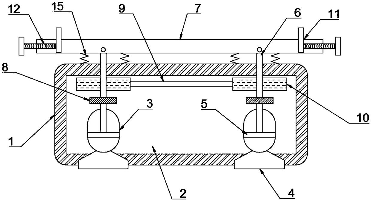
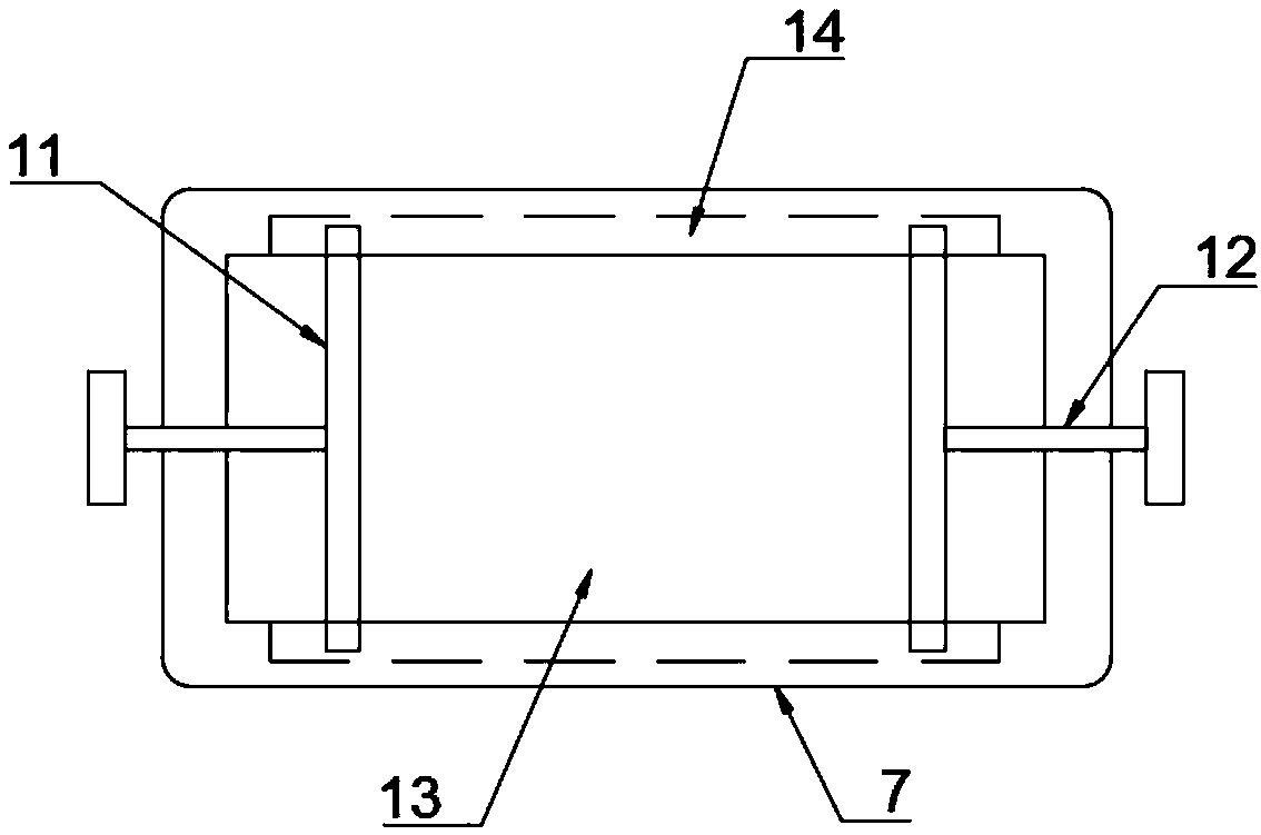
[0024] refer to Figure 1-2 , an anti-dumping placement device, including a placement seat 1, a cavity 2 is opened inside the placement seat 1, and two airbags 3 are fixed on the inner bottom of the cavity 2, and each airbag 3 is made of hard plastic material , to avoid the change of the volume of the airbag 3 due to the change of the gas, the inner wall of each airbag 3 is slidably connected with a piston 5, and the upper side wall of each piston 5 is fixedly connected with a moving rod 6, and the two moving rods 6 The upper end runs through the upper side wall of the airbag 3 and the inner top wall of the cavity 2 to the upper side wall of the placement seat 1, and the lower side wall of each air bag 3 is fixed with a suction cup 4, which is convenient for the suction cup 4 and the placement seat. 1 The suction between the placement surfaces, and then complete the suction and fixation of the placement seat 1, each suction cup 4 is connected with the inside of the air bag 3, ...

Embodiment 2

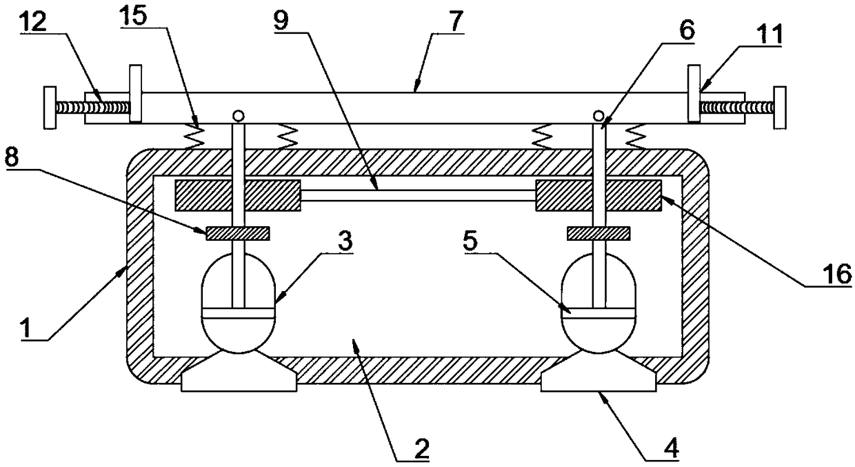
[0032] refer to image 3 , the anti-movement mechanism includes a fixed plate 9 fixedly connected to the inner wall of the cavity 2, and second magnets 16 are fixedly connected to both sides of the fixed plate 9, and each second magnet 16 is provided with a slide, each slide Matching the size and position of one of the moving rods 6, the upper end of each moving rod 6 passes through the sliding opening and is slidably connected with the inner wall of the sliding opening, and the outer wall of each moving rod 6 is sleeved with a first magnet 8, Each first magnet 8 is all positioned at the lower side of the second magnet 16, and the magnetic properties of the first magnet 8 and the second magnet 16 are opposite. When the other side of 7 pulls the moving rod 6 to move upwards, the first magnet 8 moves to one side of the second magnet 16, and the repulsive force of the second magnet 16 to the first magnet 8 prevents the moving rod 6 from moving upwards, avoiding An increase in the ...


PUM


Abstract

The invention discloses an anti-toppling placement device which comprises a placement seat. A cavity is formed in the placement seat. Two airbags are fixed to the inner bottom of the cavity. Each airbag is made of a hard plastic material. A piston is in sliding connection to the inner wall of each airbag. A moving rod is fixedly connected to the upper side wall of each piston. The anti-toppling placement device has the advantages that when an object inclines, the moving rods are driven to move upwards, then the pistons are driven to move upwards, air pressure in suction cups is reduced, and therefore the suction cups and the placement face of the placement seat achieve tight suction, and the placement seat is prevented from toppling over; meanwhile, through the influence of magnets on magnetorheological fluid, the magnetorheological fluid is solidified along with the process that the magnets approach to the magnetorheological fluid to clamp the moving rods, the moving rods are prevented from moving, and the tendency of toppling is further avoided; and the stability of the placed object is guaranteed, and safety is higher.

Description

technical field [0001] The invention relates to the technical field of placing devices, in particular to an anti-dumping placing device. Background technique [0002] The placement device, such as the common placement frame and support frame in daily life, plays the role of fixing, supporting and placing the object, ensuring the stability of the object placement. [0003] In order to ensure convenient movement, the current placement device generally sets rollers at the bottom for movement, or it is placed directly in one place and directly contacts with the placement surface. Tilting to one side together, or causing the object to fall to one side together with the shelf or support frame, resulting in the object being broken, such as the common display screen or fan, which is only supported by the base, and there is no anti-dumping device installed, which is easy Objects fall and become damaged. [0004] For this reason, we propose an anti-dumping placement device to solve ...

Claims


Application Information

Patent Timeline
Patent Type & Authority Applications(China)
IPC IPC(8): F16M13/02F16M11/04F16B47/00A47B96/07A47B97/00
CPCA47B96/07A47B97/00F16B47/00F16M11/041F16M13/022
Inventor 马万连
Owner 博维恩冷冻科技(苏州)有限公司
Why Eureka
Try Eureka