Optical measuring system based on integrating sphere

An optical measurement system and integrating sphere technology, applied in the field of optical measurement, can solve the problems of extremely high requirements on the laser incident direction, influence of laser parameter measurement, low system integration, etc., and achieve laser speckle suppression, low manufacturing cost, and system structure. compact effect

Inactive Publication Date: 2018-12-11
合肥中科九衡科技有限公司
View PDF3 Cites 1 Cited by
  • Summary
  • Abstract
  • Description
  • Claims
  • Application Information

AI Technical Summary

Problems solved by technology

When laser measurement is performed in the prior art, the main measurement parameters include energy parameters, time parameters and spectral parameters. The measurement method is usually to use multiple pieces of flat glass to divide the laser into multiple beams, and inject them into different measuring instruments to measure different parameters. This measurement method needs to be individually adjusted for each flat glass, which is time-consuming and labor-intensive, the system integration is not high, and the requirements for the incident direction of the laser are extremely high, and measurement errors are prone to occur
Using an integrating sphere can measure the energy parameters, time parameters and spectral parameters of the laser synchronously. It is easy to integrate and has a high tolerance to the incident direction of the laser. However, the laser has good temporal coherence and spatial coherence. The laser introduced into the integrating sphere passes through After the diffuse reflection inside the sphere, an irregular intensity distribution will be formed at the exit, which is called speckle. The existence of speckle will have a certain impact on the measurement of laser parameters.

Method used


Image

  • Optical measuring system based on integrating sphere
  • Optical measuring system based on integrating sphere
  • Optical measuring system based on integrating sphere

Examples


Embodiment

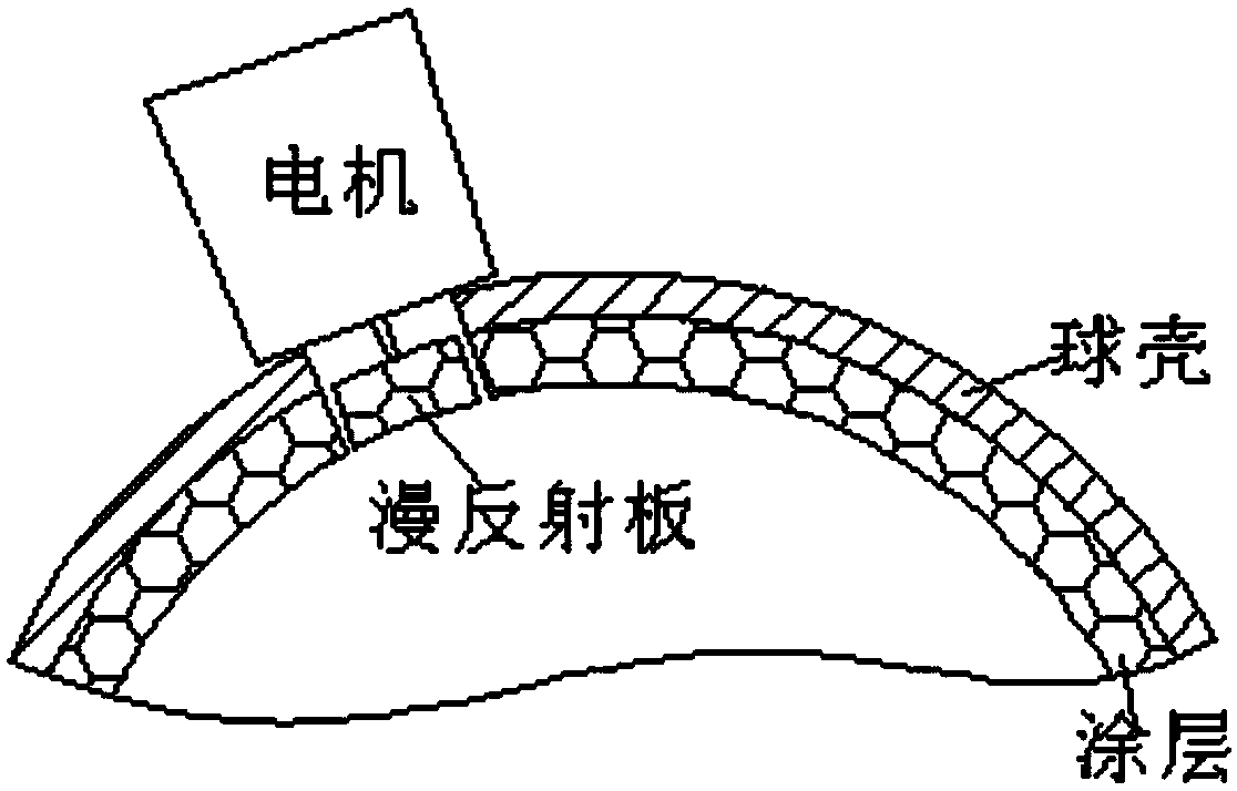
[0023] Such as figure 1 As shown, the optical measurement system based on the integrating sphere includes an incident laser, a beam reducer, an integrating sphere, an energy meter, a photoelectric tube, a fiber coupler, a computer, an oscilloscope and a spectrometer, and the integrating sphere is provided with a light inlet and Three light outlets, the beam reducer is set at the light inlet, the energy meter, photocell and fiber coupler are respectively set at the three light outlets, the output of the energy meter is connected to the computer, and the output of the phototube is connected to the oscilloscope , the output end of the fiber coupler is connected to the spectrometer, the inner wall of the integrating sphere is coated with diffuse reflection coating, and the inner wall of the integrating sphere is provided with a diffuse reflection plate, and a micro DC motor is installed outside the spherical shell of the integrating sphere, and the rotor of the micro DC motor Pass...


PUM


Abstract

The invention discloses an optical measuring system based on an integrating sphere. The system comprises an incident laser, a beam narrowing mirror, the integrating sphere, an energy meter, a photoelectric tube, a fiber coupler, a computer, an oscilloscope and a spectrometer. The integrating sphere is provided with a light in port and three light out ports. The beam narrowing mirror is arranged atthe light in port, and the energy meter, the photoelectric tube and the fiber coupler are arranged at the three light out ports. An output end of the energy meter is connected to the computer, and anoutput end of the photoelectric tube is connected to the oscilloscope. An output end of the fiber coupler is connected with to spectrometer, an inner wall of the integrating sphere is coated with a diffuse reflection coating, and at the same time, a diffuse reflection plate is arranged on the inner wall of the integrating sphere. A micro DC motor is mounted outside an integrating sphere shell, and a rotor of the micro DC motor passes through the integrating sphere shell to connect the diffuse reflection plate. When the system is applied, the energy parameters, time parameters and spectral parameters of the laser can be measured synchronously, the laser speckle can be effectively suppressed, the parameter measurement accuracy can be improved, and the manufacturing cost can be reduced.

Description

technical field [0001] The invention relates to the technical field of optical measurement, in particular to an optical measurement system based on an integrating sphere. Background technique [0002] Optical measurement is a measurement technology combining photoelectric technology and mechanical measurement, which includes the measurement of ordinary light sources, LED light sources and lasers. When laser measurement is performed in the prior art, the main measurement parameters include energy parameters, time parameters and spectral parameters. The measurement method is usually to use multiple pieces of flat glass to divide the laser into multiple beams, and inject them into different measuring instruments to measure different parameters. This measurement method needs to be individually adjusted for each flat glass, which is time-consuming and labor-intensive, the system integration is not high, and the requirements for the incident direction of the laser are extremely hi...

Claims


Application Information

Patent Timeline
Patent Type & Authority Applications(China)
IPC IPC(8): G01J1/42G01J3/28
CPCG01J1/4257G01J3/28
Inventor 庞伟伟史秀丽李基李威王梦冉方翠翠
Owner 合肥中科九衡科技有限公司
Why Eureka
Try Eureka