LED light bar illumination test mechanism

A technology of LED light strips and testing institutions, applied in the direction of lamp testing, etc., can solve the problems of low detection accuracy, limit detection efficiency, increase time cost, etc., and achieve the effect of increasing detection accuracy, improving detection accuracy, and saving time and cost.

Inactive Publication Date: 2018-12-11
SUZHOU RIHE TECH
View PDF7 Cites 2 Cited by
  • Summary
  • Abstract
  • Description
  • Claims
  • Application Information

AI Technical Summary

Problems solved by technology

In the prior art, two positive and negative test probes connected to the power supply are usually used to detect LED light strips one by one. The positive test probe is connected to the positive pole of the circuit board, and the negative test probe is connected to the negative pole of the circuit board. Whether all the LED lights are on normally, but in the actual test process, testing the LED light strips one by one will greatly limit the detection efficiency, increase the time cost, and the detection accuracy is low

Method used


Image

  • LED light bar illumination test mechanism
  • LED light bar illumination test mechanism

Examples


Embodiment

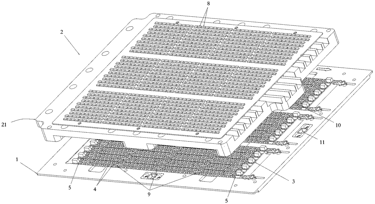
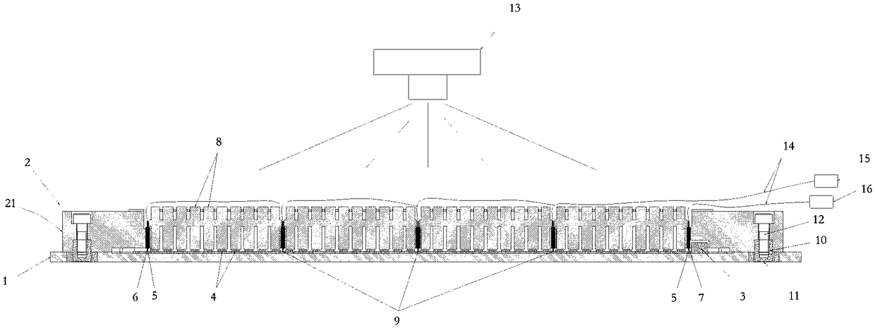
[0022] Shown in conjunction with the accompanying drawings is a specific implementation of the LED light bar lighting test mechanism of the present invention. First, it includes a lower mold 1 and a circuit board 3 arranged on the lower mold 1. The circuit boards 3 are arranged in parallel Thirty groups of test units are arranged, and each group of test units includes forty LED light-emitting lamps 4 distributed laterally at intervals, and the distance between two adjacent LED light-emitting lamps 4 in the test units is equal.

[0023] The circuit board 3 is provided with two main contacts 5 and three auxiliary contacts 9 corresponding to each group of test units, as shown in the figure, corresponding to any group of test units, two main contacts 5 are respectively set On the outside of the corresponding LED lights 4 on both sides, an auxiliary contact 9 is provided between two adjacent LED lights 4 every ten LED lights 4 .

[0024] Secondly, the testing mechanism also include...


PUM


Abstract

The invention discloses an LED light bar illumination test mechanism. The test mechanism comprises a lower die, a circuit board arranged on the lower die, an upper die and a shooting device arranged over the upper die, groups of test units are arranged on the circuit board in parallel, each group of test units comprises multiple LED lamps, the circuit board is provided with at least two contacts corresponding to each group of test units, each contact comprises main contacts arranged in the group of test units corresponding to the outers sides of the LED lamps at the two sides, the upper die comprises an upper die seat, the upper die seat is provided with anode and cathode probes making contact with the corresponding main contacts, of each group of test units, for conduction, light guide sheets arranged in one to one correspondence with the LED lamps are fixed on the upper die seat in a penetrated way, and a light source emitted by the LED lamps is guided to the to the shooting device by the light guide sheets. Thus, the groups of test units can be tested simultaneously, the detection efficiency is improved, manual operation is not needed in the detection process, the time cost is reduced, and the detection precision is high.

Description

technical field [0001] The invention relates to an LED light bar lighting test mechanism. Background technique [0002] During the production and processing of LED light strips, it is usually necessary to perform a lighting test on the LED light-emitting lights on the circuit board. By testing whether all the LED light-emitting lights are normally lit, it is judged whether the factory quality of the LED light strips is qualified. In the prior art, two positive and negative test probes connected to the power supply are usually used to detect LED light strips one by one. The positive test probe is connected to the positive pole of the circuit board, and the negative test probe is connected to the negative pole of the circuit board. Whether all the LED lights are on normally, but in the actual test process, testing the LED light strips one by one will greatly limit the detection efficiency, increase the time cost, and the detection accuracy is low. Contents of the invention ...

Claims


Application Information

Patent Timeline
IPC IPC(8): G01R31/44
CPCG01R31/44
Inventor 谢钰峰覃福正
Owner SUZHOU RIHE TECH
Why Eureka
Try Eureka