Supercharge Your Innovation With Domain-Expert AI Agents!

A high-voltage current-limiting fuse having a signaling device

A fuse and high-voltage technology, applied in emergency protection devices, electrical components, circuits, etc., can solve problems such as out-of-control, damage, and inaccurate measurement of controlled electrical appliances, and achieve stable layout, reasonable structure, and reliable work.

Active Publication Date: 2018-12-11
扬州国电华欣电气设备有限公司
View PDF4 Cites 0 Cited by
  • Summary
  • Abstract
  • Description
  • Claims
  • Application Information

AI Technical Summary

Problems solved by technology

[0003] Specifically, the high-voltage voltage transformer directly connected to the grid may be damaged due to internal faults and line overvoltage; on the one hand, in the metering circuit, the disappearance of the secondary voltage signal of the voltage transformer will lead to inaccurate metering; on the other hand On the one hand, in the control loop, the disappearance of the secondary power supply of the voltage transformer will cause the controlled electrical appliances to run out of control

Method used

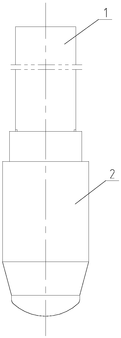
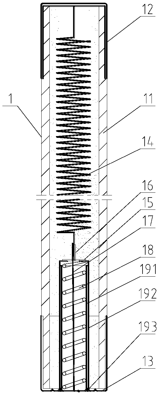
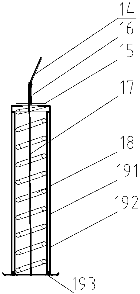

Image

  • A high-voltage current-limiting fuse having a signaling device
  • A high-voltage current-limiting fuse having a signaling device
  • A high-voltage current-limiting fuse having a signaling device

Examples


Embodiment 1

[0048] Embodiment 1, the housing 221 is provided with a pair of weak structures 2211, the first electrode 224 and the second electrode 225 are accommodated in the pair of weak structures 2211 respectively, and the container 222 is made of non-conductive non-metallic material. In this way, the first electrode and the second electrode are simultaneously subjected to external force, pierce the weak structure, and contact the electrolyte to realize energy supply; the container is made of non-conductive non-metallic material, which is corrosion-resistant and improves the storage time of the battery structure.

[0049] The bottom ends of the first electrode 224 and the second electrode 225 are both tapered. In this way, the first electrode and the second electrode can break through the weak structure more easily, ensuring reliable energy supply.

Embodiment 2

[0050] Embodiment 2, the housing 221 is provided with a weak structure 22 and a housing hole 2212, the electrode 1 224 is accommodated in the weak structure 2211, and the electrode 2 225 is accommodated in the housing hole 2212 In, and connected with the container 222, the container 222 is made of conductive non-metallic material. In this embodiment, the container is made of a conductive non-metallic material. After being connected to the second electrode, the second electrode and the container form an electrode as a whole. In this way, the second electrode is fixed, and it is only necessary to push the first electrode into the container to contact the electrolyte. A battery structure can be formed, which makes the entire battery structure more streamlined and improves the reliability of the battery structure.

[0051] The bottom end of the first electrode 4 is conical. In this way, the electrode one can break through the weak structure more easily, ensuring reliable energy s...


PUM


Abstract

A high-voltage current-limiting fuse having a signaling device. The invention relates to the field of fuse structure, in particular to an improvement in the structure of a fuse having a signaling device. A high-voltage current-limiting fuse with the signaling device has the advantages of compact structure and easy machining, a striker can be well and stably arranged in a fuse tube, when overvoltage or overcurrent occurs, the high-voltage current-limiting fuse can fuse so as to eject the striker so that the signaling device is turned on and triggered. The high-voltage current-limiting fuse includes a fuse body and a signaling device; The electrode 1 and the electrode 2 are positioned directly below the striker; The alarm is fixedly connected with the base, and the electrode 1 and the electrode 2 are respectively connected with the alarm through a lead. The weak structure is a receiving groove, the sidewall of the receiving groove passes through the container, and the bottom of the receiving groove is located in the electrolyte, and the thickness of the bottom of the receiving groove gradually becomes thick from the center to the edge. The high-voltage current-limiting fuse has reasonable structure and reliable operation.

Description

technical field [0001] The invention relates to the field of fuse structure, in particular to the improvement of the structure of the fuse with a signaling device. Background technique [0002] At present, for the voltage transformers installed on outdoor overhead lines, because the existing AC high-voltage current-limiting fuses (referred to as P-type fuses) used to protect high-voltage voltage transformers are not suitable for outdoor installation environments, the direct hanging method is often used. , which brings a greater hidden danger to line safety. [0003] Specifically, the high-voltage voltage transformer directly connected to the grid may be damaged due to internal faults and line overvoltage; on the one hand, in the metering circuit, the disappearance of the secondary voltage signal of the voltage transformer will lead to inaccurate metering; on the other hand On the one hand, in the control loop, the disappearance of the secondary power supply of the voltage t...

Claims


Application Information

Patent Timeline
IPC IPC(8): H01H85/30H01H85/042
CPCH01H85/042H01H85/30Y02E60/10
Inventor 周鑫殷阿明
Owner 扬州国电华欣电气设备有限公司
Features
  • R&D
  • Intellectual Property
  • Life Sciences
  • Materials
  • Tech Scout
  • Unparalleled Data Quality
  • Higher Quality Content
  • 60% Fewer Hallucinations
Learn More