A vertical motor assembly apparatus and a motor assembly method

A technology for assembling equipment and vertical motors, which is used in electromechanical devices, manufacturing motor generators, electrical components, etc., can solve the problems of unfavorable large-scale promotion, low installation accuracy, and high work intensity, and achieves low price and installation accuracy. High and reduced workload

Pending Publication Date: 2018-12-11
浙江巨龙自动化设备股份有限公司
View PDF7 Cites 1 Cited by
  • Summary
  • Abstract
  • Description
  • Claims
  • Application Information

AI Technical Summary

Problems solved by technology

[0002] Most of the current vertical motor assembly is manually assembled, with a large workload and high work intensity, and the installation accuracy is not high
There are also vertical motors installed by machines, but the existing machines are expensive and complicated to operate, which is not conducive to large-scale promotion

Method used


Image

  • A vertical motor assembly apparatus and a motor assembly method
  • A vertical motor assembly apparatus and a motor assembly method

Examples


Embodiment 1

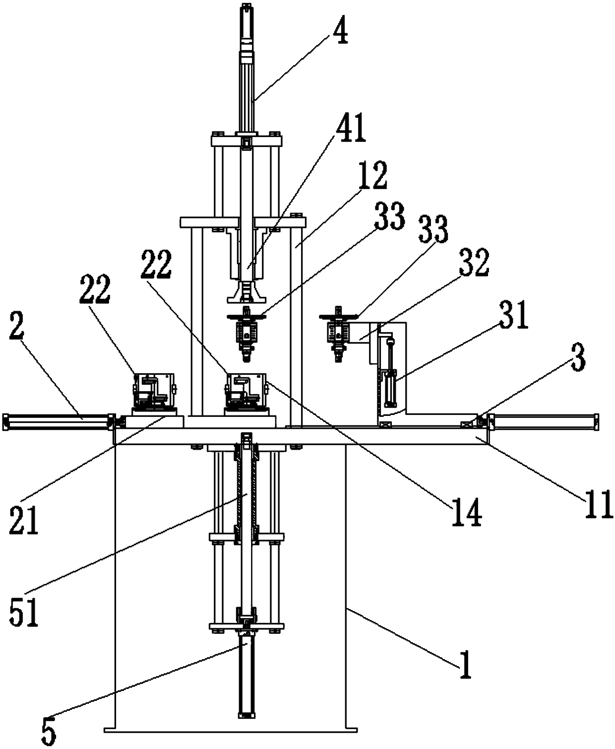
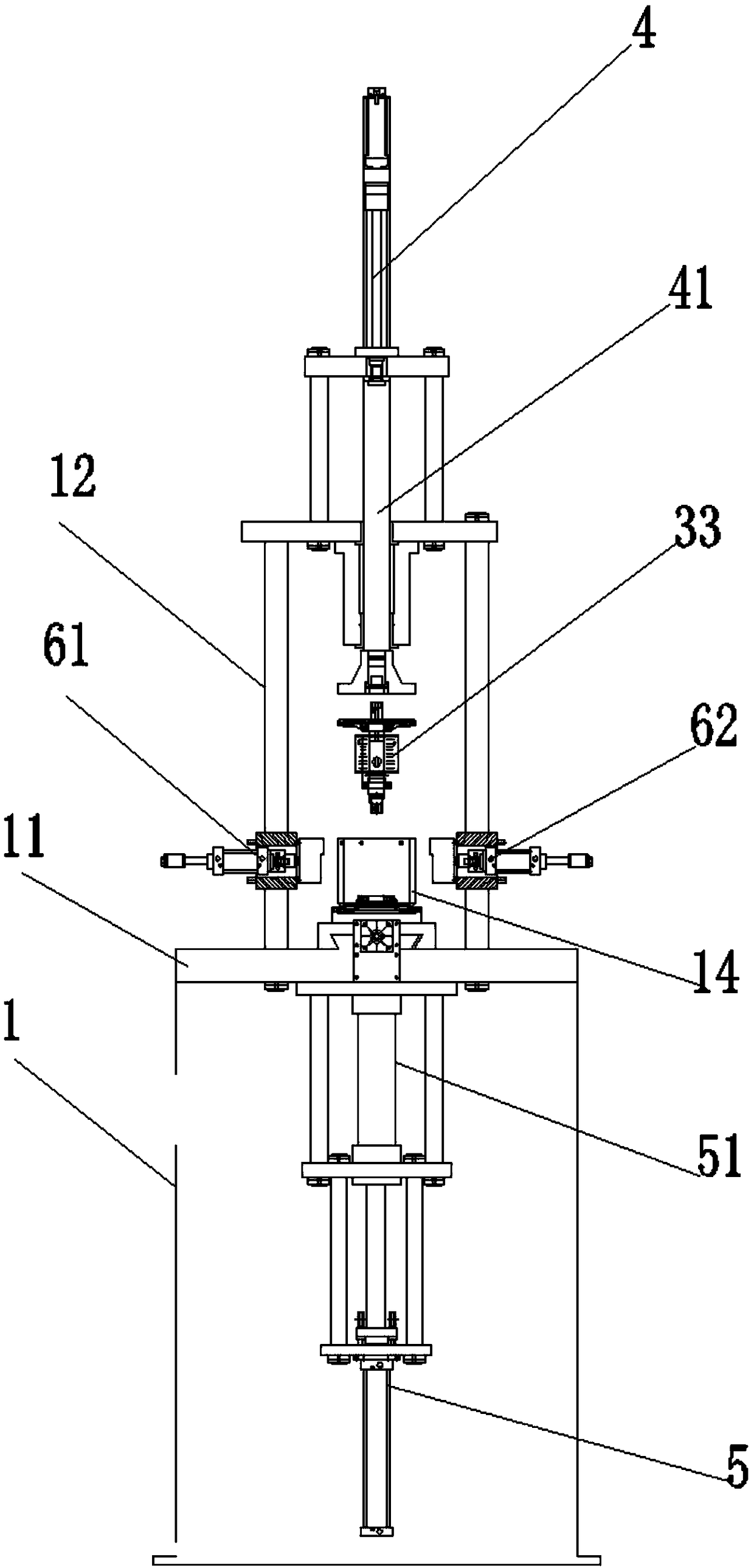
[0033] Example 1, see figure 1 and figure 2 , a preferred embodiment of the invention, a vertical motor assembly equipment, including a frame 1, a work platform 11 is set on the frame, and a positioning center 14 is set on the work platform. The improvement is that it also includes:

[0034] The upper mandrel pushing mechanism and the lower mandrel pushing mechanism are arranged oppositely up and down, the upper mandrel pushing mechanism 4 and the lower mandrel pushing mechanism 5 are respectively used to push the upper mandrel 41 downward and the lower mandrel 51 upward;

[0035] The positioning center 14 is located between the upper spindle pushing mechanism and the lower spindle pushing mechanism, and the positioning center 14 coincides with the center line of the upper spindle pushing mechanism and the lower spindle pushing mechanism;

[0036] The stator assembly pushing mechanism and the rotor assembly pushing mechanism respectively arranged on the front and rear sides ...

Embodiment approach

[0041] As an embodiment of the present invention, both the stator assembly pushing mechanism and the rotor assembly pushing mechanism include a station seat 21 and a driving power assembly connected with the station seat, and the pushing power assembly is used to push the stator assembly or rotor on the station seat The assembly is pushed horizontally toward the positioning center 14, and a longitudinal movement mechanism 31 for driving the rotor assembly in the station seat to move up and down is provided between the station seat of the rotor assembly pushing mechanism and the driving power assembly of the rotor assembly pushing mechanism. The driving power assembly includes a linear cylinder arranged horizontally and a second electromagnetic valve connected with the linear cylinder arranged horizontally, and the second electromagnetic valve is connected with a controller. The longitudinal movement mechanism 31 includes a linear motor and a solenoid valve, which is also connec...


PUM


Abstract

The invention relates to a vertical motor assembly apparatus, comprising a frame, a positioning center is arranged on the frame, and the vertical motor assembly further comprises an upper mandrel pushing mechanism and a lower mandrel pushing mechanism. The positioning center is arranged between the upper spindle pushing mechanism and the lower spindle pushing mechanism, and coincides with the centerline of the upper spindle pushing mechanism and the lower spindle pushing mechanism. Stator assembly pushing mechanism and rotor assembly pushing mechanism respectively arranged at the front and rear sides of the positioning center; Left and right stator assembly clamping devices arranged on the left and right sides of the positioning center; The controller is respectively connected with an upper spindle pushing mechanism, a lower spindle pushing mechanism, a stator assembly pushing mechanism, a rotor assembly pushing mechanism and a left and right stator assembly clamping devices. Also disclosed is a motor assembly method of a vertical motor assembly apparatus. The invention can reduce the workload and the working intensity of the workers, improve the installation precision, reduce thecost and simplify the operation.

Description

technical field [0001] The invention belongs to the field of motor installation, and relates to a vertical motor assembly device, in particular to a vertical motor assembly device and a motor assembly method. Background technique [0002] Most of the current vertical motor assembly is manually assembled, which has a large workload and high work intensity, and the installation accuracy is not high. Also have vertical motor installed by machine, but existing machine cost height, complicated operation, is unfavorable for large-scale popularization. Contents of the invention [0003] In order to solve the above-mentioned technical problems, the object of the present invention is to provide a vertical motor assembly equipment and a motor assembly method, which can reduce the workload and work intensity of workers, and improve the installation accuracy, and also The cost can be reduced and the operation is simpler. [0004] A vertical motor assembly device of the present inven...

Claims


Application Information

Patent Timeline
Patent Type & Authority Applications(China)
IPC IPC(8): H02K15/00
CPCH02K15/00
Inventor 陈家乐蒋国为章文强陈翔黎宏锋
Owner 浙江巨龙自动化设备股份有限公司
Why Eureka
Try Eureka