A heat dissipation device of an Internet of Things exchange
A technology of heat dissipation device and switch, applied in cooling/ventilation/heating transformation, chassis/cabinet/drawer parts, electrical components, etc. Achieve the effect of slowing vibration, accelerating heat dissipation, ensuring operation safety and service life
- Summary
- Abstract
- Description
- Claims
- Application Information
AI Technical Summary
Problems solved by technology
Method used
Image
Examples
Embodiment 1
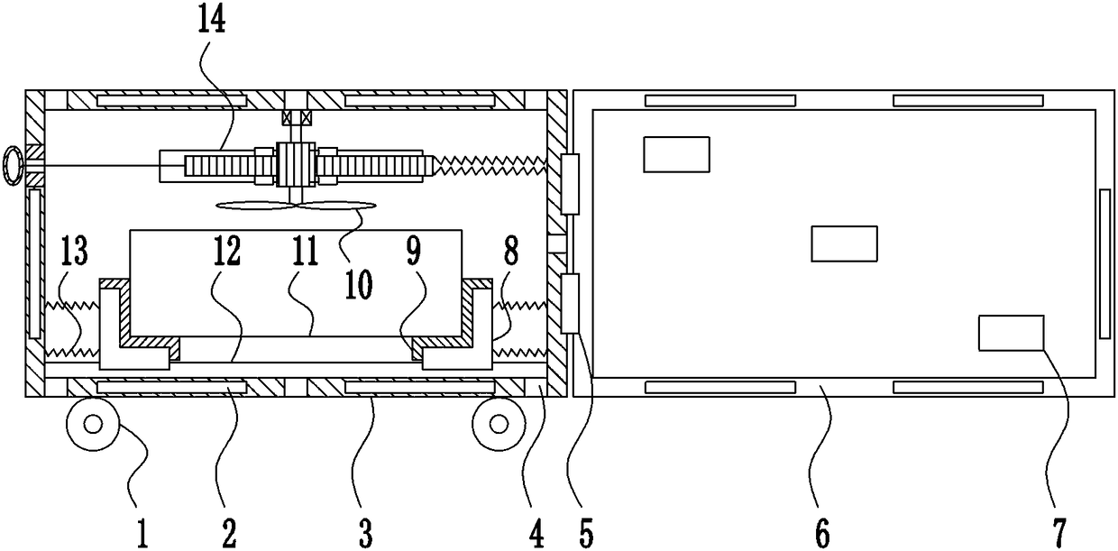
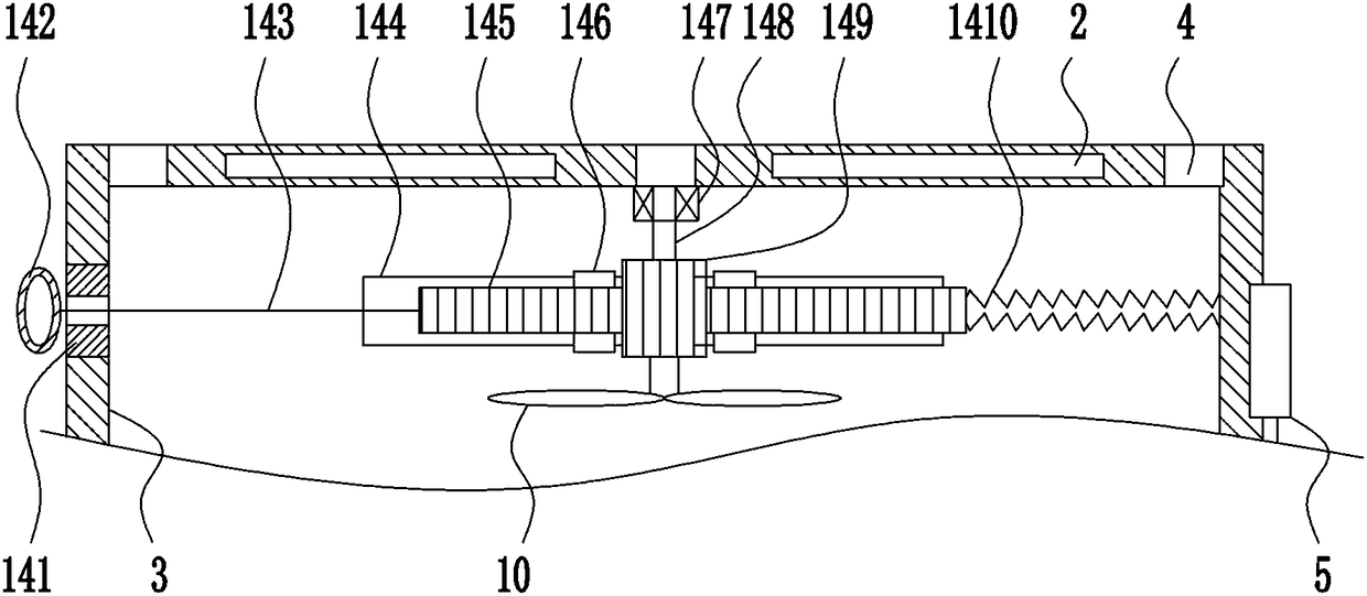
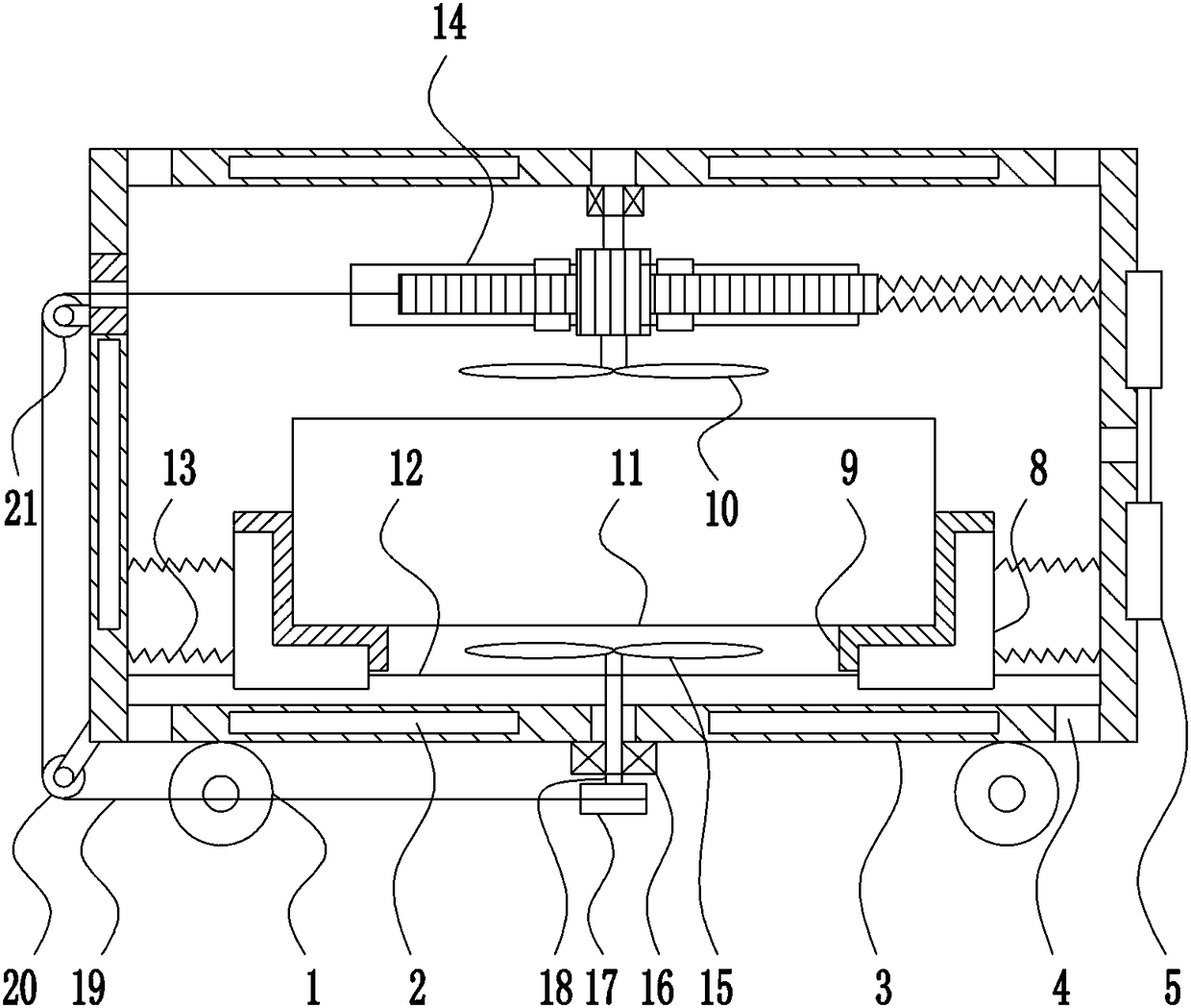
[0029] A cooling device for an Internet of Things switch, such as Figure 1-4 As shown, it includes roller 1, magnet 2, box body 3, hinge 5, box door 6, L-shaped slider 8, rubber pad 9, first blade 10, switch 11, first slide rail 12, first elastic Part 13 and rotating device 14, the bottom of the box body 3 is provided with a roller 1, the right side of the box body 3 is connected with the box door 6 through the hinge 5, the box door 6 is evenly opened with a ventilation hole 7, the box door 6 and the box body 3 Magnets 2 are arranged on the upper, lower and left walls of the front side of the box body, perforations 4 are uniformly opened on the wall of the box body 3, first slide rails 12 are arranged on the front and rear sides of the inner bottom of the box body 3, and the first slide rail 12 is provided with L The first elastic member 13 is connected between the outside of the L-shaped slider 8 and the inner wall of the box body 3, the inner side of the L-shaped slider 8 i...
Embodiment 2
[0031] A cooling device for an Internet of Things switch, such as Figure 1-4As shown, it includes roller 1, magnet 2, box body 3, hinge 5, box door 6, L-shaped slider 8, rubber pad 9, first blade 10, switch 11, first slide rail 12, first elastic Part 13 and rotating device 14, the bottom of the box body 3 is provided with a roller 1, the right side of the box body 3 is connected with the box door 6 through the hinge 5, the box door 6 is evenly opened with a ventilation hole 7, the box door 6 and the box body 3 Magnets 2 are arranged on the upper, lower and left walls of the front side of the box body, perforations 4 are uniformly opened on the wall of the box body 3, first slide rails 12 are arranged on the front and rear sides of the inner bottom of the box body 3, and the first slide rail 12 is provided with L The first elastic member 13 is connected between the outside of the L-shaped slider 8 and the inner wall of the box body 3, the inner side of the L-shaped slider 8 is...
Embodiment 3
[0034] A cooling device for an Internet of Things switch, such as Figure 1-4 As shown, it includes roller 1, magnet 2, box body 3, hinge 5, box door 6, L-shaped slider 8, rubber pad 9, first blade 10, switch 11, first slide rail 12, first elastic Part 13 and rotating device 14, the bottom of the box body 3 is provided with a roller 1, the right side of the box body 3 is connected with the box door 6 through the hinge 5, the box door 6 is evenly opened with a ventilation hole 7, the box door 6 and the box body 3 Magnets 2 are arranged on the upper, lower and left walls of the front side of the box body, perforations 4 are uniformly opened on the wall of the box body 3, first slide rails 12 are arranged on the front and rear sides of the inner bottom of the box body 3, and the first slide rail 12 is provided with L The first elastic member 13 is connected between the outside of the L-shaped slider 8 and the inner wall of the box body 3, the inner side of the L-shaped slider 8 i...
PUM
 Abstract
Description
Claims
Application Information
 - R&D
- Intellectual Property
- Life Sciences
- Materials
- Tech Scout
- Unparalleled Data Quality
- Higher Quality Content
- 60% Fewer Hallucinations
Browse by: Latest US Patents, China's latest patents, Technical Efficacy Thesaurus, Application Domain, Technology Topic, Popular Technical Reports.
© 2025 PatSnap. All rights reserved.Legal|Privacy policy|Modern Slavery Act Transparency Statement|Sitemap|About US| Contact US: help@patsnap.com


