
A hole-drilling device for special-shaped die-casting parts

A technology for die casting and hole processing, which is applied in metal processing equipment, metal processing mechanical parts, manufacturing tools, etc., and can solve problems such as large errors, inability to open holes at multiple angles, and inaccurate positioning of castings.

Active Publication Date: 2020-11-06
赵硕
View PDF5 Cites 0 Cited by
  • Summary
  • Abstract
  • Description
  • Claims
  • Application Information

AI Technical Summary

Problems solved by technology

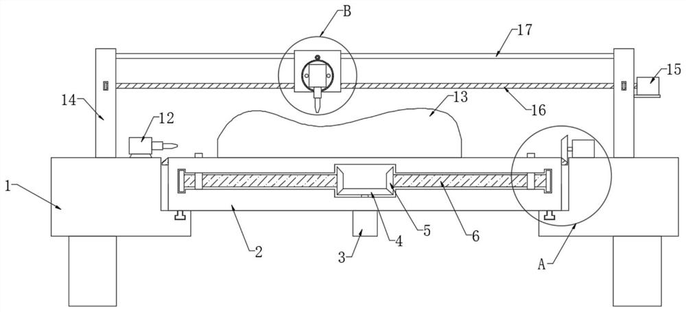
[0004] The purpose of the present invention is to solve the shortcomings of inaccurate casting positioning, large errors, inability to open holes at multiple angles and limitations in the prior art, and proposes a special-shaped die casting hole opening processing device

Method used


Image

  • A hole-drilling device for special-shaped die-casting parts
  • A hole-drilling device for special-shaped die-casting parts
  • A hole-drilling device for special-shaped die-casting parts

Examples


Embodiment Construction

[0026] The following will clearly and completely describe the technical solutions in the embodiments of the present invention with reference to the accompanying drawings in the embodiments of the present invention. Obviously, the described embodiments are only some, not all, embodiments of the present invention.

[0027] In describing the present invention, it should be understood that the terms "upper", "lower", "front", "rear", "left", "right", "top", "bottom", "inner", " The orientation or positional relationship indicated by "outside", etc. is based on the orientation or positional relationship shown in the drawings, and is only for the convenience of describing the present invention and simplifying the description, rather than indicating or implying that the referred device or element must have a specific orientation, so as to Specific orientation configurations and operations, therefore, are not to be construed as limitations on the invention.

[0028] refer to Figure ...


PUM


Abstract

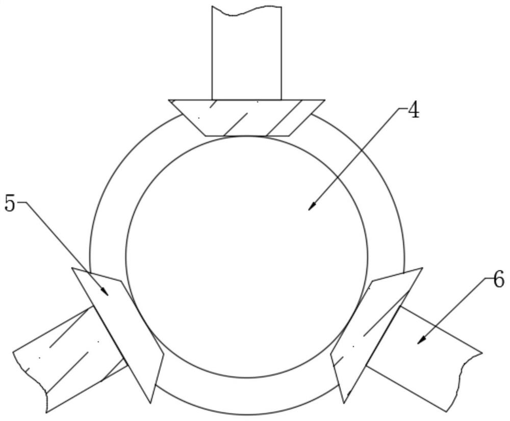
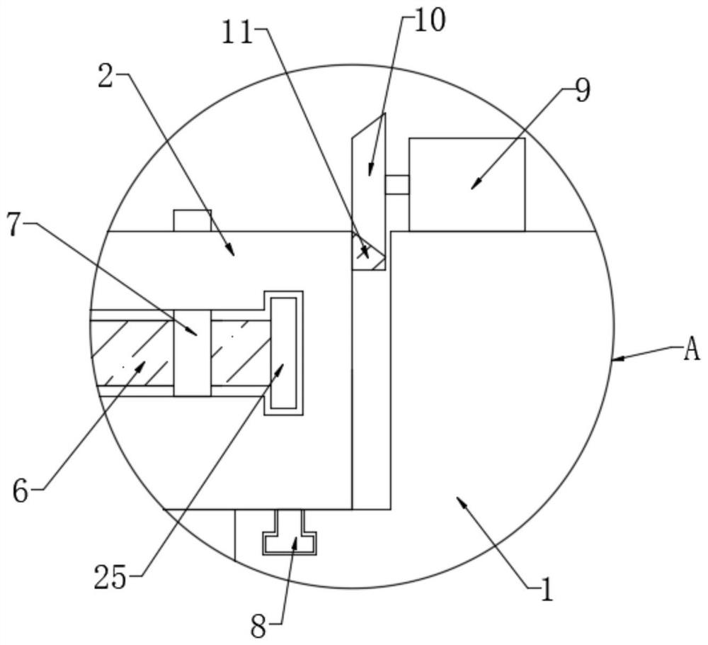
The invention discloses a trepanning device for a specially-shaped die casting. The trepanning device comprises a handling frame and a baseplate, wherein a processing part is placed on the top wall ofthe baseplate; a cavity and three transverse grooves are formed in the baseplate; the three transverse grooves are symmetrically distributed on the outer side of the cavity and communicate with the cavity; a first servo motor is mounted on the bottom wall of the baseplate; a driving end of the first servo motor extends into the cavity and is equipped with a first bevel gear; a fixed threaded rodis arranged in each transverse groove; and the end, close to the cavity, of each fixed threaded rod extends into the cavity and is equipped with a second bevel gear. Owing to the arrangement of all structures, the processing part can be trepanned in a horizontal direction and a vertical direction; meanwhile, an inclined hole can be formed in the processing part as required, so that actual operation demands are met, the flexibility of the trepanning device is improved, and the operation range of the trepanning device is broadened; and the trepanning device has the characteristics of being simple in structure and easy to operate.

Description

technical field [0001] The invention relates to the technical field of casting processing, in particular to a device for processing holes of special-shaped die castings. Background technique [0002] Castings are metal shaped objects obtained by various casting methods, that is, the smelted liquid metal is poured into the pre-prepared mold by pouring, injection, suction or other casting methods, and after cooling, it is polished and other subsequent processing methods , the resulting object has a certain shape, size and performance. [0003] After the casting is formed, it needs to be drilled. When drilling, a drilling tool or a drill is used for processing. The existing processing device has the following disadvantages in use: the positioning is inaccurate due to the irregular shape of the casting, resulting in errors Larger, it is difficult to process multi-angle holes, and the operation is limited, so it needs to be improved. Contents of the invention [0004] The obj...

Claims


Application Information

Patent Timeline
Patent Type & Authority Patents(China)
IPC IPC(8): B23B39/16B23Q1/25
CPCB23B39/16B23Q1/25
Inventor 赵硕
Owner 赵硕
Learn More