Eureka AIR delivers breakthrough ideas for toughest innovation challenges, trusted by R&D personnel around the world.

A tool for installing and disassembling long bolts inside equipment

A long bolt assembly and disassembly technology, which is applied in the field of long bolt assembly and disassembly tools inside the equipment, can solve the problems of difficulty in the accurate installation position of bolts, affecting the efficiency of maintenance work, and inconvenient installation and disassembly of bolts, so as to ensure the reliability of work and service life Effect

Inactive Publication Date: 2020-04-14
马新然
View PDF10 Cites 0 Cited by
  • Summary
  • Abstract
  • Description
  • Claims
  • Application Information

AI Technical Summary

Problems solved by technology

After detailed observation, it was found that due to the compact layout of the power distribution cabinet, the power components are located inside the power distribution cabinet, and it is extremely inconvenient to install and remove bolts
The existing problems mainly include: first, because the installation location is inside the power distribution cabinet, it is difficult to determine the exact installation location of the bolts; second, in order to ensure that the bolt length is sufficient, generally longer bolts are selected for fixing, but the length It is difficult to align the nuts with common tools when the bolts are disassembled and installed
This will cause inconvenience in the replacement and installation of internal components, and even affect the reliability and safety of internal components, seriously affecting the efficiency of maintenance work

Method used


Image

  • A tool for installing and disassembling long bolts inside equipment
  • A tool for installing and disassembling long bolts inside equipment
  • A tool for installing and disassembling long bolts inside equipment

Examples


Embodiment Construction

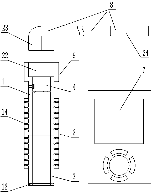
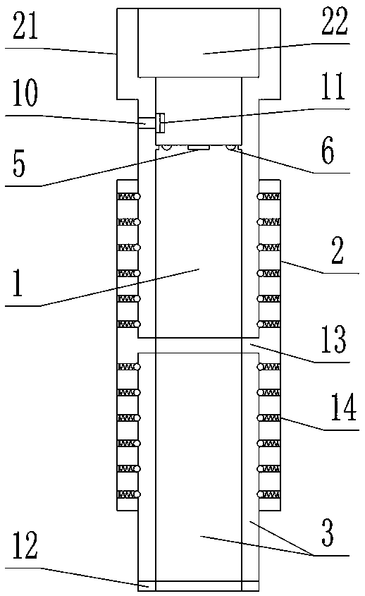
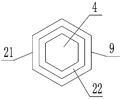
[0030] As shown in the figure, the tool for installing and disassembling long bolts inside the device includes an input sleeve 1 , a connecting sleeve 2 and an output sleeve 3 that extend in the same direction and are hollow. The inner wall of the output end of the output sleeve is a regular hexagon that fits with the nut. The input sleeve is fitted with the input section of the inner cavity of the connecting sleeve and the two can only slide in the relative axial direction. The output sleeve and the connecting sleeve The output section of the inner chamber is plug-fitted and the two can only be slid relative to each other in the axial direction. A wireless monitor 4 is installed in the inner cavity of the input end of the input sleeve, a camera 5 facing the inner cavity of the output sleeve is installed on the wireless monitor, and a supplementary light 6 facing the inner cavity of the output sleeve is also installed on the wireless monitor. . This patent also includes a wir...


PUM


Abstract

The invention discloses a tool for assembling and disassembling a long bolt inside equipment. The tool comprises an input sleeve, a connecting sleeve and an output sleeve which extend in the same direction and are hollow, the inner wall of the output end of the output sleeve is in a regular hexagon sleeved with a nut in a cooperating mode, the input sleeve is in insertion fit with an input sectionof an inner cavity of the connecting sleeve, moreover, the input sleeve and the connecting sleeve can only be in sliding fit relative to the axial direction, the output sleeve is in insertion fit with an output section of the inner cavity of the connecting sleeve, moreover, the output sleeve and the connecting sleeve can only be in sliding fit relative to the axial direction, a wireless monitor is installed in an inner cavity of the input end of the input sleeve, the wireless monitor is provided with a camera and a light supplementing lamp, and the tool further comprises a wireless displayer.The tool has the advantages that the installation position of the bolt can be quickly found, the position of a screw can be accurately positioned, the nut can be carried and can accurately sleeve thescrew, the nut can be tightened or loosened quickly, after the nut is screwed out, the nut can be effectively connected to ensure that the nut does not fall off, and the operation is simple.

Description

technical field [0001] The invention relates to a tool for installing and disassembling long bolts inside equipment. Background technique [0002] The power distribution cabinet is a transfer device for the grid line to supply power to the residential quarters. Whether the power distribution cabinet is reliable or not will directly determine the quality of the power supply. In residential quarters, maintenance personnel of power companies are often seen maintaining power distribution cabinets. At present, a variety of electrical equipment is centrally installed in the power distribution cabinet to ensure the normal power supply of the power supply line. After detailed observation, it was found that due to the compact layout of the power distribution device cabinet, the power components are located inside the power distribution device cabinet, and it is extremely inconvenient to install and remove bolts. The existing problems mainly include: first, because the installation ...

Claims


Application Information

Patent Timeline
Patent Type & Authority Patents(China)
IPC IPC(8): B25B27/14B25B23/18
CPCB25B23/18B25B27/14
Inventor 马新然
Owner 马新然
Why Eureka
Eureka Blog
Learn More