Injection mold with rapid positioning function

A technology of injection mold and function, which is applied in the field of injection mold with rapid positioning function, can solve the problems of uneven movement of ejector pin plate, waste of time and energy, bending and breaking of ejector pin, etc. Leakage, the effect of ensuring the stability of use

Inactive Publication Date: 2020-11-20
TAIZHOU VOCATIONAL COLLEGE OF SCI & TECH
View PDF11 Cites 1 Cited by
  • Summary
  • Abstract
  • Description
  • Claims
  • Application Information

AI Technical Summary

Problems solved by technology

[0003] At present, when the existing injection mold is set up, it needs to waste a lot of time and energy to determine the installation position of the mold, so that the nozzle position of the mold is on the same axis as the injection nozzle of the injection molding machine, and the existing injection mold is in the After a long time of use, the surface of the limiting column will produce putty impurities, which will cause the thimble plate to move up and down on the surface of the limiting column. If it is serious, it may cause the two ends of the thimble plate to fail to maintain balance, resulting in inclination, which will cause the thimble to bend. break off, so that the mold can not be used normally, so we designed an injection mold with quick positioning function to solve the above problems

Method used


Image

  • Injection mold with rapid positioning function
  • Injection mold with rapid positioning function
  • Injection mold with rapid positioning function

Examples


Embodiment Construction

[0028] The following will clearly and completely describe the technical solutions in the embodiments of the present invention with reference to the accompanying drawings in the embodiments of the present invention. Obviously, the described embodiments are only some, not all, embodiments of the present invention. Based on the embodiments of the present invention, all other embodiments obtained by persons of ordinary skill in the art without making creative efforts belong to the protection scope of the present invention.

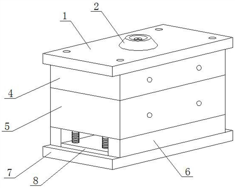
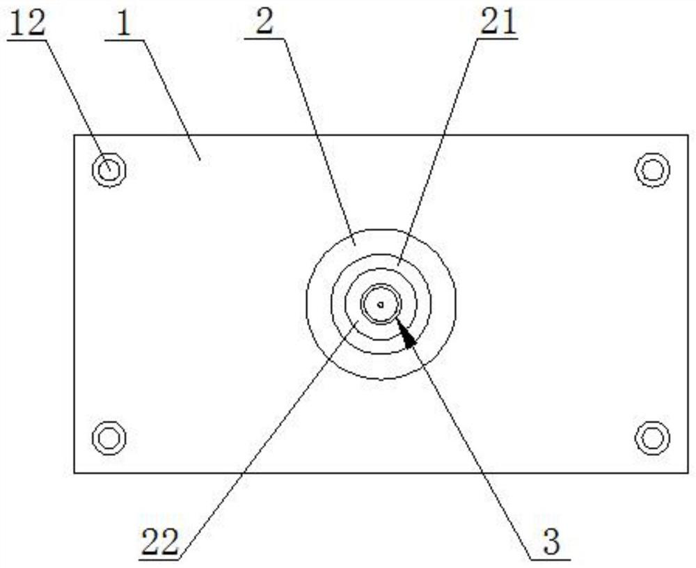
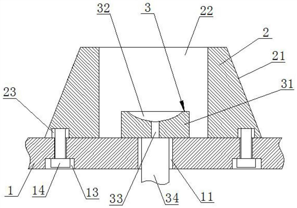
[0029] see Figure 1-5 , an injection mold with rapid positioning function, including upper template 1, see Figure 1-5 , the surface of the upper template 1 is provided with a central hole 11, a first countersunk hole 12 and a second countersink 13, and the first countersunk hole 12 is used to fix the installation position of the upper template 1 and the upper mold 4 by other screws 14, The second countersunk holes 13 are distributed equidistantly in a ring,...


PUM


Abstract

The invention discloses an injection mold with a rapid positioning function, and belongs to the technical field of injection molds. A center hole, first counterbores and second counterbores are formedin the surface of an upper mold plate, and a positioning seat is fixedly connected to the second counterbores through screws; an inclined face is arranged on the side face of the positioning seat, apositioning hole is formed in the central position of the positioning seat, and a gate brush is sleeved with the positioning hole; and an upper mold body is fixedly arranged on the other surface of the upper mold plate, and a lower mold body is connected with the other surface of the upper mold body in a clamped mode. According to the injection mold with the rapid positioning function, when the mold is set up, the mounting position of the mold can be rapidly determined through the positioning seat, so that the mold setting up efficiency of the mold is greatly improved; and an arranged ejectorpin plate has the effect of automatically clearing putty on the surfaces of limiting columns after the mold is used for a long time, so that the moving stability of the ejector pin plate is guaranteed, the service life of ejector pins is prolonged, and then the use stability of the mold is guaranteed.

Description

technical field [0001] The invention relates to the technical field of injection molds, and more specifically, relates to an injection mold with a rapid positioning function. Background technique [0002] Injection molding, also known as injection molding, is a molding method of injection and molding. The advantages of injection molding method are fast production speed, high efficiency, and automatic operation. It is suitable for mass production and molding processing of products with complex shapes. field. [0003] At present, when the existing injection mold is set up, it needs to waste a lot of time and energy to determine the installation position of the mold, so that the nozzle position of the mold is on the same axis as the injection nozzle of the injection molding machine, and the existing injection mold is in the After a long time of use, the surface of the limiting column will produce putty impurities, which will cause the thimble plate to move up and down on the s...

Claims


Application Information

Patent Timeline
Patent Type & Authority Applications(China)
IPC IPC(8): B29C45/26B29C45/17B29C33/30B29C45/18
CPCB29C45/1742B29C45/18B29C45/2606
Inventor 褚建忠
Owner TAIZHOU VOCATIONAL COLLEGE OF SCI & TECH
Why Eureka
Try Eureka