
A rotary device for magnetic flux pump

A technology for rotating devices and pumps, applied in the direction of magnetic objects, superconducting magnets/coils, electrical components, etc., can solve problems that affect experimental efficiency, high cost, and laborious, and achieve the effect of ensuring experimental efficiency and saving costs

Active Publication Date: 2021-04-06
SHAOYANG UNIV
View PDF4 Cites 0 Cited by
  • Summary
  • Abstract
  • Description
  • Claims
  • Application Information

AI Technical Summary

Problems solved by technology

[0008] The setting of the above-mentioned rotating device has relatively large defects. Since the setting of the magnetic flux pump needs to match the power supply current required by the superconducting magnet, a large number of experiments are required to determine what size and waveform of the magnetic field can induce induction in the superconductor. In each experiment, the shape and size of the permanent magnet may be different. In this way, it is necessary to replace the rotating device or re-groove the outer circumferential surface of the rotating device for each test to find the best permanent magnet shape and combination. This method may require dozens or even hundreds of experiments. This processing method is time-consuming, laborious, and costly, and affects the efficiency of the experiment.

Method used


Image

  • A rotary device for magnetic flux pump
  • A rotary device for magnetic flux pump
  • A rotary device for magnetic flux pump

Examples


Embodiment Construction

[0036] In order to clearly illustrate the design concept of the present invention, the present invention will be described below in conjunction with examples.

[0037] In order to enable those skilled in the art to better understand the solutions of the present invention, the technical solutions in the embodiments of the present invention are clearly and completely described below in conjunction with the accompanying drawings in the examples of the present invention. Obviously, the described examples are only the present invention Some examples, but not all examples. Based on the examples in the present invention, all other implementations obtained by those skilled in the art without making creative efforts shall fall within the protection scope of the present invention.

[0038] In the description of this embodiment, the orientations or positional relationships indicated by the terms "front", "rear", "left", and "right" are all based on the orientations or positional relation...


PUM


Abstract

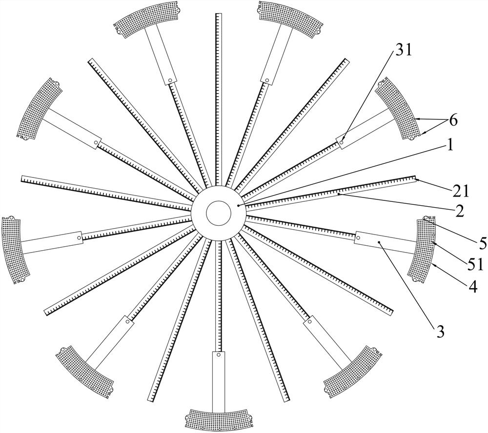
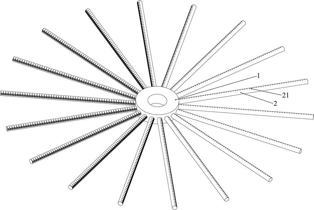
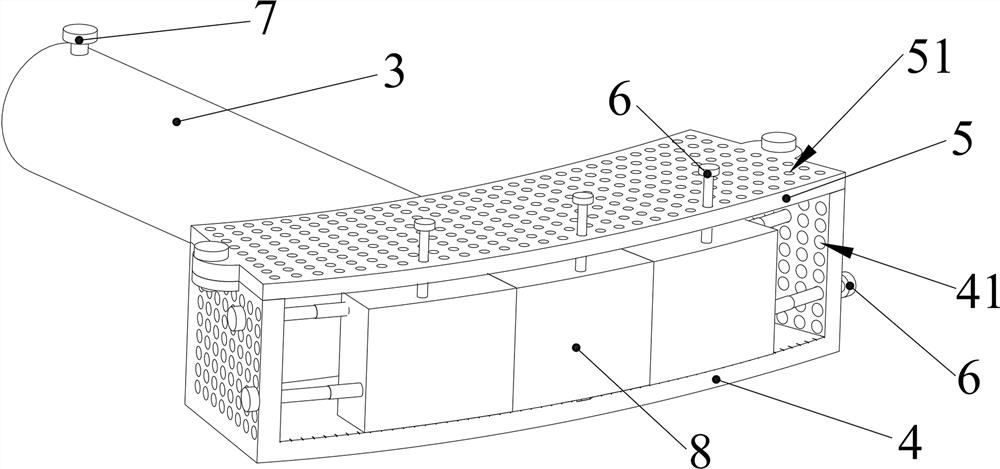
The invention discloses a rotating device for a magnetic flux pump, comprising: a mounting frame and a magnet mounting structure; the mounting frame includes a mounting ring and a mounting rod set on the rotating shaft, and several mounting rods are detachably fixed on the mounting ring. and evenly distributed along the outer circumferential surface of the mounting ring; the magnet mounting structure includes a sleeve, a magnet mounting shell and screws, one end of the sleeve is fixedly connected to the magnet mounting shell, and the other end of the sleeve is detachably set and fixed on the mounting rod; On the magnet mounting shell, an opening for loading the permanent magnet is provided at the end away from the sleeve, and a plurality of first threaded holes are densely arranged on the first end surface of the magnet mounting shell, and the first threaded holes are used to fix the permanent magnet with screws In the inner cavity of the magnet mounting housing. When using the rotating device of the present invention to conduct experiments to determine the maximum induced current of the superconducting coil, the rotating device does not need to be repeatedly processed, and the installation of the permanent magnet can be quickly completed to ensure the experimental efficiency and quickly determine the shape and installation position of the permanent magnet.

Description

technical field [0001] The invention relates to the field of superconducting magnet power supply, in particular to a rotating device for a magnetic flux pump. Background technique [0002] Superconducting materials refer to materials that exhibit the properties of zero resistance and repulsive magnetic field lines under certain low temperature conditions. The most widespread application of superconducting technology is in the manufacture of magnets. Compared with conventional magnets, the most prominent feature of superconducting magnets is that their magnetic fields are very strong. Usually, the magnetic fields of one to twenty tesla are generated by superconducting magnets. The zero-resistance property of superconductivity is highlighted here. For such a strong magnet, the working current is often as high as hundreds to thousands of amperes, but the heat generated by the magnet is negligible. The electric power of ordinary electromagnets with the same magnetic field str...

Claims


Application Information

Patent Timeline
Patent Type & Authority Patents(China)
IPC IPC(8): H01F6/00
CPCH01F6/005
Inventor 彭志华谢义元邹长春
Owner SHAOYANG UNIV
Learn More