Composite grid manufacturing equipment and manufacturing method and grid thereof

A composite material and manufacturing equipment technology, applied in the field of FRP grating production equipment, can solve the problems affecting the structural strength of the FRP grating itself, difficult to ensure the lifting force, product loss, etc., to achieve stable and effective demoulding methods, fast layout, The effect of high production efficiency

Pending Publication Date: 2018-12-14
浙江德毅隆科技股份有限公司
View PDF5 Cites 0 Cited by
  • Summary
  • Abstract
  • Description
  • Claims
  • Application Information

AI Technical Summary

Problems solved by technology

The yarn in the groove of the mold may also be bent and fluffy, and if the yarn is too fluffy, it will also affect the structural strength of the produced FRP grating
[0004] FRP grating needs to be demolded after the mold is formed, but FRP grating has unique characteristics compared with other products, and its own size is often large, especially the horizontal and horizontal dimensions. The traditional demoulding method is to use the cylinder top Lifting, but it is difficult to ensure the balance of the jacking force, it is easy to cause difficulty in demoulding, and unnecessary loss of products

Method used


Image

  • Composite grid manufacturing equipment and manufacturing method and grid thereof
  • Composite grid manufacturing equipment and manufacturing method and grid thereof
  • Composite grid manufacturing equipment and manufacturing method and grid thereof

Examples


Embodiment Construction

[0060] Below in conjunction with specific embodiment, content of the present invention is described in further detail:

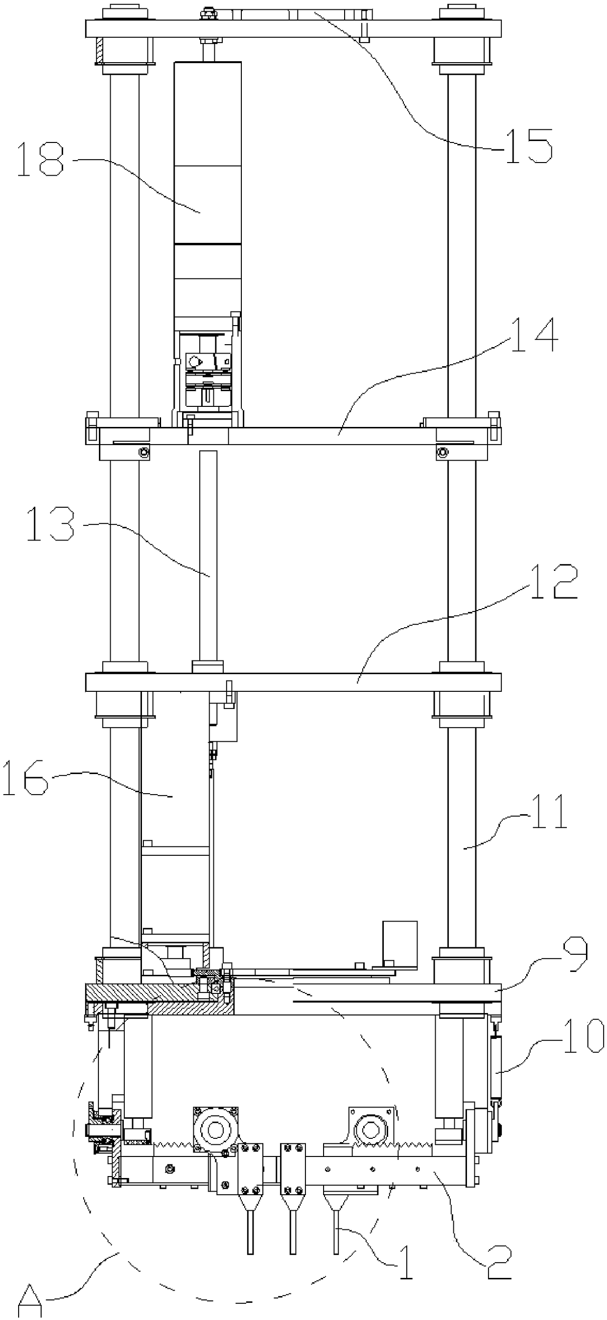
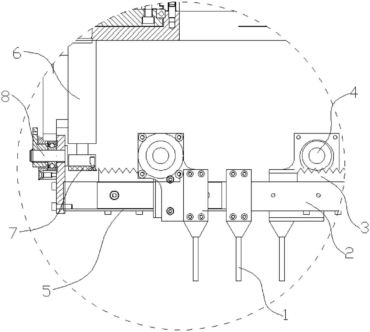
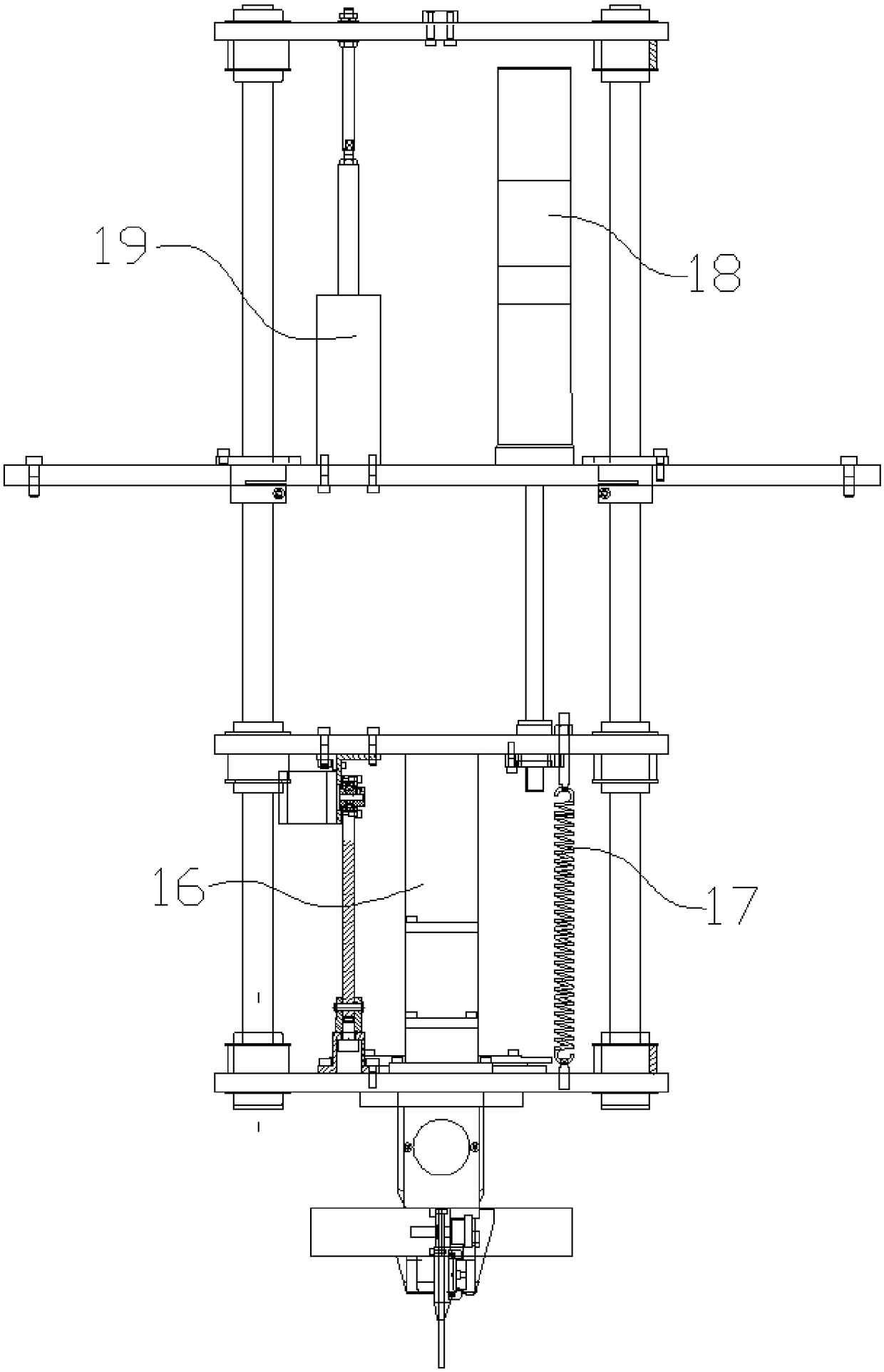
[0061] The yarn running mechanism includes: the yarn distributing tube 1, which has a hollow pipe for the yarn to pass through; the plane traveling mechanism, which drives the yarn distributing tube 1 to translate in the horizontal plane, and has at least translational freedom along the x-axis and y-axis degree; the vibration mechanism applies periodic vibration to the cloth tube 1.

[0062] The x-axis and y-axis are two horizontal lines that cross each other perpendicularly. Such as Figure 9 As shown, the yarn cloth tube 1 needs to extend into the groove in the mold 24 . figure 1 , image 3 . Figure 4 The plane running gear is hidden. Figure 9 is a schematic diagram of the whole. The material of the yarn is glass fiber.

[0063] The beneficial effect of adopting the above technical solution is: the yarn cloth tube ensures that the yarn will not b...


PUM


Abstract

The invention discloses composite grid manufacturing equipment and manufacturing method and a grid thereof. The composite grid manufacturing equipment comprises a yarn running mechanism, a compactingdevice and a die release jacking device. The yarn running mechanism drives yarn to penetrate through a hollow pipeline of a yarn distributing pipe to be arranged in a cross mode in a groove of a die.The yarn distributing pipe has translational degrees of freedom in the x-axis and y-axis directions in the horizontal plane. The compacting device compacts the yarn in the groove. A yarn pressing plate driven by a pneumatic vibrator stretches into the groove in the die to make contact with the yarn in the groove. The bottom of the groove and the lower surface of the die are provided with through holes, a jacking pin upwards penetrates through the through holes, and the composite grid is separated from the die. Component force of rotation of a horizontal screw rod and movement of an inclined block is used for pushing a lifting plate to move upwards, and the jacking pin is lifted. The composite grid manufacturing equipment and manufacturing method are adopted, firstly, the yarn is fast arranged in the groove in the die through the yarn distributing pipe, the compacting device compacts the yarn in the groove, after solidification, the finished product of the composite grid is formed, andthe jacking pin is lifted for die release.

Description

technical field [0001] The invention relates to the field of glass fiber reinforced plastic grid production equipment, in particular to a composite material grid manufacturing equipment, a manufacturing method and the grid. Background technique [0002] The FRP grating is molded in a mold. The FRP grating is composed of yarn and resin. The resin is the filling material of the FRP grating, and the cross-cut yarns are the internal materials of the FRP grating. The number of holes in the FRP grating means that there are many vertically intersecting yarns of the FRP grating. If the yarn is arranged manually on the mold, the efficiency is low and the quality cannot be guaranteed. It is necessary to use automated equipment to arrange the yarn on the mold efficiently. In the prior art, the position of the longitudinal yarn is generally fixed, the horizontal yarn reciprocates, and the mold moves forward along the direction of the longitudinal yarn. The final mold is continuous and...

Claims


Application Information

Patent Timeline
Patent Type & Authority Applications(China)
IPC IPC(8): B29C70/30B29C70/38B29C70/54
CPCB29C70/30B29C70/38B29C70/54B29C70/541
Inventor 侯恒
Owner 浙江德毅隆科技股份有限公司
Why Eureka
Try Eureka