
LNG transport ship rudder sleeve installation method

An installation method and technology of rudder sleeves, which are applied in the field of installation of rudder sleeves for LNG transport ships, can solve problems such as increased workload of positioning and inspection, many welds at joints, misalignment of closed joints, etc.

Active Publication Date: 2018-12-14
CHINA MERCHANTS HEAVY IND JIANGSU +1
View PDF7 Cites 5 Cited by
  • Summary
  • Abstract
  • Description
  • Claims
  • Application Information

AI Technical Summary

Problems solved by technology

[0003] There are several difficulties in the installation of the rudder sleeve: ① High precision is required. Before the shipyard installs the rudder sleeve, the inner and outer diameters and length of the rudder sleeve have allowances, and the installation accuracy must be completed through subsequent rough machining and finishing. Requirements; ② When installing the rudder sleeve, it involves the connection between the rudder sleeve and the steering gear cabin section, the connection between the steering gear cabin section and the main base section, and the subsequent installation of the rudder stock and rudder blades. If the installation process is improper, it will increase Large workload of positioning and inspection; ③When the involved sections are closed on the berth, the accumulation of deviations often leads to misalignment of the closing joints and out-of-tolerance gaps. The rudder sleeve is located between the rudder sleeve and the rudder blade, and the rudder sleeve is greatly affected by external forces when the LNG carrier is working, so all the joint welds between the rudder sleeve and the rudder cabin section require full penetration welding during design , and the segmental structure of the rudder sleeve and the rudder cabin is complicated, and there are many welds at the joints, resulting in serious precision out-of-tolerance after the welding is completed

Method used


Image

  • LNG transport ship rudder sleeve installation method
  • LNG transport ship rudder sleeve installation method

Examples


Embodiment Construction

[0019] Embodiments of the present invention are described in detail below, examples of which are shown in the drawings, wherein the same or similar reference numerals designate the same or similar elements or elements having the same or similar functions throughout. The embodiments described below by referring to the figures are exemplary only for explaining the present invention and should not be construed as limiting the present invention.

[0020] In the description of the present invention, unless otherwise specified and limited, it should be noted that the terms "installation", "connection" and "connection" should be understood in a broad sense, for example, it can be mechanical connection or electrical connection, or two The internal communication of a component can be directly connected or indirectly connected through an intermediary. Those of ordinary skill in the art can understand the specific meanings of the above terms according to specific situations.

[0021] re...


PUM


Abstract

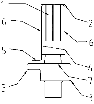
The invention relates to an LNG transport ship rudder sleeve installation method. The method features that a rudder nacelle is hoisted integrally with a rudder sleeve, and the rudder sleeve is reduceby space restriction and is easier to hoist. Installation of positioning rudder sleeve on the ship bench eliminates positioning of the rudder centerline on the segments and avoids secondary positioning and inspection; By fixing the rudder sleeve in the rudder engine room and overlaying the groove in the rudder engine room, the workload caused by the accumulated deviation of the rudder sleeve in the rudder engine room can be reduced, the work at height can be reduced, and the construction environment can be improved. As that assembly gap between the surfacing groove and the weld seam is not more than 2mm and the joint misalignment is adjusted by the fire work industry, As that saw-tooth shape horse plate is adopted for reinforce and positioning, and the welding sequence is adopted, the welding fil amount can be reduced, the welding heat input can be reduced, the welding deformation can be reduced, the installation efficiency and the installation precision can be improved, and the machining time and the cost can be reduced.

Description

technical field [0001] The invention relates to the field of ship transportation, in particular to a method for installing a rudder sleeve of an LNG transportation ship. Background technique [0002] The installation of a rudder sleeve for an LNG transport ship involves the connection between the rudder sleeve and the steering gear cabin segment, the connection between the steering gear cabin segment and the main base segment, the subsequent installation of the rudder stock and the rudder blade, and the installation of the rudder sleeve The technical requirements are as follows: the deviation between the center point of the upper end and the center point of the lower end of the actual rudder sleeve relative to the centerline of the theoretical rudder stock is not greater than 2mm in any direction, the allowable deviation of the upper end surface of the actual rudder sleeve relative to the theoretical height is 3mm, and the distance from the main engine to the center line of t...

Claims


Application Information

Patent Timeline
IPC IPC(8): B63B9/00
CPCB63B71/00
Inventor 张辉宋宪磊周文梅先志
Owner CHINA MERCHANTS HEAVY IND JIANGSU
Learn More